- 您現(xiàn)在的位置:買賣IC網(wǎng) > PDF目錄377000 > DSP1629 TVS 400W 64V UNIDIRECT SMA PDF資料下載
參數(shù)資料
| 型號(hào): | DSP1629 |
| 英文描述: | TVS 400W 64V UNIDIRECT SMA |
| 中文描述: | DSP1629數(shù)字信號(hào)處理器 |
| 文件頁(yè)數(shù): | 110/126頁(yè) |
| 文件大小: | 1993K |
| 代理商: | DSP1629 |
第1頁(yè)第2頁(yè)第3頁(yè)第4頁(yè)第5頁(yè)第6頁(yè)第7頁(yè)第8頁(yè)第9頁(yè)第10頁(yè)第11頁(yè)第12頁(yè)第13頁(yè)第14頁(yè)第15頁(yè)第16頁(yè)第17頁(yè)第18頁(yè)第19頁(yè)第20頁(yè)第21頁(yè)第22頁(yè)第23頁(yè)第24頁(yè)第25頁(yè)第26頁(yè)第27頁(yè)第28頁(yè)第29頁(yè)第30頁(yè)第31頁(yè)第32頁(yè)第33頁(yè)第34頁(yè)第35頁(yè)第36頁(yè)第37頁(yè)第38頁(yè)第39頁(yè)第40頁(yè)第41頁(yè)第42頁(yè)第43頁(yè)第44頁(yè)第45頁(yè)第46頁(yè)第47頁(yè)第48頁(yè)第49頁(yè)第50頁(yè)第51頁(yè)第52頁(yè)第53頁(yè)第54頁(yè)第55頁(yè)第56頁(yè)第57頁(yè)第58頁(yè)第59頁(yè)第60頁(yè)第61頁(yè)第62頁(yè)第63頁(yè)第64頁(yè)第65頁(yè)第66頁(yè)第67頁(yè)第68頁(yè)第69頁(yè)第70頁(yè)第71頁(yè)第72頁(yè)第73頁(yè)第74頁(yè)第75頁(yè)第76頁(yè)第77頁(yè)第78頁(yè)第79頁(yè)第80頁(yè)第81頁(yè)第82頁(yè)第83頁(yè)第84頁(yè)第85頁(yè)第86頁(yè)第87頁(yè)第88頁(yè)第89頁(yè)第90頁(yè)第91頁(yè)第92頁(yè)第93頁(yè)第94頁(yè)第95頁(yè)第96頁(yè)第97頁(yè)第98頁(yè)第99頁(yè)第100頁(yè)第101頁(yè)第102頁(yè)第103頁(yè)第104頁(yè)第105頁(yè)第106頁(yè)第107頁(yè)第108頁(yè)第109頁(yè)當(dāng)前第110頁(yè)第111頁(yè)第112頁(yè)第113頁(yè)第114頁(yè)第115頁(yè)第116頁(yè)第117頁(yè)第118頁(yè)第119頁(yè)第120頁(yè)第121頁(yè)第122頁(yè)第123頁(yè)第124頁(yè)第125頁(yè)第126頁(yè)
Data Sheet
March 2000
DSP1629 Digital Signal Processor
110
Lucent Technologies Inc.
11 Timing Characteristics for 2.7 V Operation
(continued)
11.8 PHIF Specifications
For the PHIF, read means read by the external user (output by the DSP); write is similarly defined. The 8-bit reads/
writes are identical to one-half of a 16-bit access.
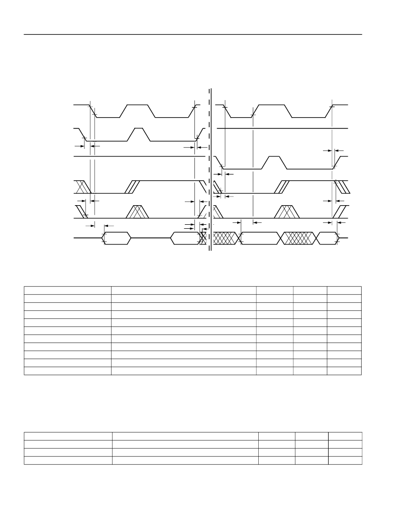
Figure 47. PHIF IntelMode Signaling (Read and Write) Timing Diagram
*
This timing diagram for the PHIF port shows accesses using the PCSN signal to initiate and complete a transaction. The transactions can
also be initiated and completed with the PIDS and PODS signals. An output transaction (read) is initiated by PCSN or PODS going low, which-
ever comes last. For example, the timing requirements referenced to PCSN going low, t45 and t49, should be referenced to PODS going low,
if PODS goes low after PCSN. An output transaction is completed by PCSN or PODS going high, whichever comes first. An input transaction
is initiated by PCSN or PIDS going low, whichever comes last. An input transaction is completed by PCSN or PIDS going high, whichever
comes first. All requirements referenced to PCSN apply to PIDS or PODS, if PIDS or PODS is the controlling signal.
Table 124. Timing Requirements for PHIF IntelMode Signaling
Abbreviated Reference
t41
t42
t43
t44
t45*
t46*
t47*
t48*
t51*
t52*
Parameter
Min
0
0
0
0
4
0
6
0
10
4
Max
—
—
—
—
—
—
—
—
—
—
Unit
ns
ns
ns
ns
ns
ns
ns
ns
ns
ns
PODS to PCSN Setup (low to low)
PCSN to PODS Hold (high to high)
PIDS to PCSN Setup (low to low)
PCSN to PIDS Hold (high to high)
PSTAT to PCSN Setup (valid to low)
PCSN to PSTAT Hold (high to invalid)
PBSEL to PCSN Setup (valid to low)
PCSN to PBSEL Hold (high to invalid)
PB Write to PCSN Setup (valid to high)
PCSN to PB Write Hold (high to invalid)
Table 125. Timing Characteristics for PHIF IntelMode Signaling
Abbreviated Reference
t49*
t50*
t154
Parameter
Min
—
0
—
Max
12
—
8
Unit
ns
ns
ns
PCSN to PB Read (low to valid)
PCSN to PB Read Hold (high to invalid)
PCSN to PB Read 3-state (high to 3-state)
5-4036 (F)
PCSN
t41
t42
t43
t45
t46
t49
t50
t154
16-bit READ
16-bit WRITE
PODS
PIDS
PBSEL
PSTAT
PB[7:0]
t47
t51
t52
t48
t44
V
IH–
V
IL–
V
IH–
V
IL–
V
IH–
V
IL–
V
IH–
V
IL–
V
IH–
V
IL–
V
IH–
V
IL–
相關(guān)PDF資料 |
PDF描述 |
|---|---|
| DSP16410C | TVS 400W 7.0V UNIDIRECT SMA |
| DSP16410 | 16-bit fixed point DSP with Flash |
| DSP25-16AR | Phase-leg Rectifier Diode |
| DSP25 | Phase-leg Rectifier Diode |
| DSP25-12A | Phase-leg Rectifier Diode |
相關(guān)代理商/技術(shù)參數(shù) |
參數(shù)描述 |
|---|---|
| DSP1629BA10K10IT | 制造商:未知廠家 制造商全稱:未知廠家 功能描述:DSP|16-BIT|CMOS|BGA|144PIN|PLASTIC |
| DSP1629BA10K12.5IR | 制造商:未知廠家 制造商全稱:未知廠家 功能描述:16-Bit Digital Signal Processor |
| DSP1629BA10K16.7IT | 制造商:未知廠家 制造商全稱:未知廠家 功能描述:DSP|16-BIT|CMOS|BGA|144PIN|PLASTIC |
| DSP1629BA10K19.2IR | 制造商:未知廠家 制造商全稱:未知廠家 功能描述:16-Bit Digital Signal Processor |
| DSP1629BA16K10IT | 制造商:未知廠家 制造商全稱:未知廠家 功能描述:DSP|16-BIT|CMOS|BGA|144PIN|PLASTIC |
發(fā)布緊急采購(gòu),3分鐘左右您將得到回復(fù)。