- 您現在的位置:買賣IC網 > PDF目錄378513 > CY7C954DX (Cypress Semiconductor Corp.) ATM HOTLink Transceiver(ATM 熱接插收發(fā)器) PDF資料下載
參數資料
| 型號: | CY7C954DX |
| 廠商: | Cypress Semiconductor Corp. |
| 英文描述: | ATM HOTLink Transceiver(ATM 熱接插收發(fā)器) |
| 中文描述: | 自動柜員機的HOTLink收發(fā)器(自動柜員機熱接插收發(fā)器) |
| 文件頁數: | 11/42頁 |
| 文件大小: | 484K |
| 代理商: | CY7C954DX |
第1頁第2頁第3頁第4頁第5頁第6頁第7頁第8頁第9頁第10頁當前第11頁第12頁第13頁第14頁第15頁第16頁第17頁第18頁第19頁第20頁第21頁第22頁第23頁第24頁第25頁第26頁第27頁第28頁第29頁第30頁第31頁第32頁第33頁第34頁第35頁第36頁第37頁第38頁第39頁第40頁第41頁第42頁
CY7C954DX
PRELIMINARY
11
CY7B923 HOTLink Transmitter, which uses the ANSI standard
8B/10B character set. The data, command, and exception
character encoding are listed in the Data and Special Charac-
ter code tables (
Tables 8
and
9
) found near the end of this data
sheet.
When the TXSOC bit (as read from the Transmit FIFO) is
HIGH, an extra character is inserted into the data stream. This
extra character is always a Special Character code (see
Table
9
) that is used to inform the remote receiver that the immedi-
ately following character should be interpreted differently from
its normal meaning. The associated character present on
TXDATA[x:0] is always encoded as a data character.
The 100b (TXSOC = 1, TXSC/D* = 0, and TXSVS = 0), 110b
and 111b combinations are used as markers for the start of a
cell, frame, or packet of data being sent across the interface.
When a character is read from the Transmit FIFO with these
bits set, a C8.0, C9.0, or C10.0 Special Character code is sent
to the encoder prior to sending the associated data character.
The 101b encoding has the same function as the 001b and
011b normal data modes. It instructs the encoder to discard
the associated data character and to replace it with a C0.7
Exception character.
The 110b encoding might be used for a context-based Start of
Cell marker (SOC with one of three modifiers), or it could be
used to expand the command space beyond that available with
the default 8B/10B code (SC/D* with a modifier). The 8B/10B
code normally supports a
data
space of 256 data characters,
and a
command
(non-data) space of twelve command charac-
ters (C0.0-C11.0 in
Table 9
). For those data links where these
few commands are not sufficient, the 110b encoding can be
used to mark the associated data as an extended command.
This expands the command space to 256 commands (in addi-
tion to some of the present twelve). When a character is read
from the Transmit FIFO with these bits set, a C9.0 Special
Character code is sent to the encoder prior to sending the data
character.
Note:
Since this character is interpreted as a
“
Start of Cell
”
marker, care should be taken in its placement. If the receiver
is in Receive Mode (00, 01,10) placements that create
“
illegal
ATM cells
”
will be discarded.
The 111b encoding might be used for a different context-based
Start of Cell marker (SOC with one of three modifiers).
When a character is read from the Transmit FIFO with these
bits set, a C10.0 Special Character is sent to the encoder prior
to sending the associated data character.
Header Error Check Generation and insertion
If HEC generation is enabled (although not really a
“
Receive
Mode
”
, this function is enabled by 00b on the RXMODE[1:0]
pins; see
Table 5
) the transmitter will overwrite the 5th byte of
each ATM cell with the appropriate internally generated HEC
code. This code is a CRC of the first four bytes in the ATM
header (the first four bytes after the Transmit Start of Cell
Marker) as is defined by the ATM Forum spec I413.
Encoder Block
The Encoder logic block performs two primary functions: en-
coding the data for serial transmission and generating BIST
(Built-In Self Test) patterns to allow at-speed link and device
testing.
BIST LFSR
The Encoder logic block operates on data stored in a register.
This register accepts information directly from the Transmit
FIFO, the Transmit Input Register, the 10/8 Byte-Packer, or
from the Transmit Control State Machine when it inserts spe-
cial characters into the data stream.
This same register is converted into a Linear-Feedback Shift-
Register (LFSR) when the Built-In Self-Test (BIST) pattern
generator is enabled (TXBISTEN* is LOW). When enabled,
this LFSR generates a 511-character sequence that includes
all Data and Special Character codes, including the explicit
violation symbols. This provides a predictable but pseudo-
random sequence that can be matched to an identical LFSR
in the Receiver.
The specific patterns generated are described in detail in the
Cypress application note
“
HOTLink Built-In Self-Test.
”
The se-
quence generated by the CY7C954DX is identical to that in the
CY7B923, CY7C924, and CY7B929, allowing interoperable
systems to be built when used at compatible serial signaling
rates and appropriate ATM Cell handling logic, since none of
these are ATM aware.
Encoder
The data passed through the Transmit FIFO and formatter, or
as received directly from the Transmit Input Register, is seldom
in a form suitable for transmission across a serial link. The
characters must usually be processed or transformed to guar-
antee:
a minimum transition density (to allow the serial receiver
PLL to extract a clock from the data stream),
a DC-balance in the signaling (to prevent baseline wander),
run-length limits in the serial data (to limit the bandwidth of
the link), and
some way to allow the remote receiver to determine the
correct character boundaries (framing).
The CY7C954DX contains an integrated 8B/10B encoder that
accepts 8-bit data characters and converts these into 10-bit
transmission characters that have been optimized for transport
on serial communications links. The operation of the 8B/10B
encoding algorithm is described in detail later in this
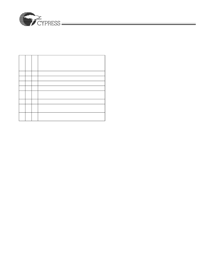
Table 1. Transmit Data Formatting
T
T
T
Data Format Operation
Normal data encode
Replace character with C0.7 Exception
Normal command encode
Replace character with C0.7 Exception
Send Start of Cell Marker Type I (C8.0) +
Data Character
Replace character with C0.7 Exception
Send Start of Cell Marker Type II (C9.0) +
Data Character
Send Start of Cell Marker Type III (C10.0) +
Data Character
0
0
0
0
1
0
0
1
1
0
0
1
0
1
0
1
1
0
1
1
0
1
1
1
相關PDF資料 |
PDF描述 |
|---|---|
| CY7C964A | Bus Interface Logic Circuit |
| CY7C964A-UM | Bus Interface Logic Circuit |
| CY7C964A-UMB | Bus Interface Logic Circuit |
| CY7C964A-ASC | Bus Interface Logic Circuit |
| CY7C964A-NC | Bus Interface Logic Circuit |
相關代理商/技術參數 |
參數描述 |
|---|---|
| CY7C955-NC | 制造商:Cypress Semiconductor 功能描述:SONET Transceiver, AX ATM-SONET/SDH Transceiver |
| CY7C960-UMB | 制造商:Cypress Semiconductor 功能描述: |
| CY7C9611-NC | 功能描述:IC PHYSICAL LAYER DEVICE RoHS:否 類別:未定義的類別 >> 其它 系列:* 標準包裝:1 系列:* 其它名稱:MS305720A |
| CY7C964A-GMB | 制造商:Rochester Electronics LLC 功能描述:- Bulk |
| CY7C964AUM | 制造商: 功能描述: 制造商:CY 功能描述: 制造商:undefined 功能描述: |
發(fā)布緊急采購,3分鐘左右您將得到回復。