- 您現(xiàn)在的位置:買賣IC網(wǎng) > PDF目錄376461 > XRT73L02 (Exar Corporation) 2 Channel E3/DS3/STS-1 Line Interface Unit(2通道 E3/DS3/STS-1線接口單元) PDF資料下載
參數(shù)資料
| 型號: | XRT73L02 |
| 廠商: | Exar Corporation |
| 英文描述: | 2 Channel E3/DS3/STS-1 Line Interface Unit(2通道 E3/DS3/STS-1線接口單元) |
| 中文描述: | 2頻道E3/DS3/STS-1線路接口單元(2通道E3/DS3/STS-1線接口單元) |
| 文件頁數(shù): | 16/62頁 |
| 文件大小: | 716K |
| 代理商: | XRT73L02 |
第1頁第2頁第3頁第4頁第5頁第6頁第7頁第8頁第9頁第10頁第11頁第12頁第13頁第14頁第15頁當前第16頁第17頁第18頁第19頁第20頁第21頁第22頁第23頁第24頁第25頁第26頁第27頁第28頁第29頁第30頁第31頁第32頁第33頁第34頁第35頁第36頁第37頁第38頁第39頁第40頁第41頁第42頁第43頁第44頁第45頁第46頁第47頁第48頁第49頁第50頁第51頁第52頁第53頁第54頁第55頁第56頁第57頁第58頁第59頁第60頁第61頁第62頁
XRT73L02
2 CHANNEL E3/DS3/STS-1 LINE INTERFACE UNIT
REV. P1.1.0
á
PRELIMINARY
12
62
TxClk_1
I
Transmit Clock Input for TPData and TNData - Channel 1:
This input pin must be driven at 34.368 MHz for E3 applications, 44.736 MHz
for DS3 applications or 51.84 MHz for SONET STS-1 applications. The
XRT73L02 uses this signal to sample the TPData_1 and TNData_1 input pins.
By default, the XRT73L02 is configured to sample these two pins on the falling
edge of this signal.
If operating in the HOST Mode, the XRT73L02 can be configured to sample
the TPData_1 and TNData_1 input pins on either the rising or falling edge of
TxClk_1.
63
TPData_1
I
Transmit Positive Data Input - Channel 1:
The XRT73L02 samples this pin on the falling edge of TxClk_1. If it samples a
"1", then it generates and transmits a positive polarity pulse to the line.
N
OTES
:
1. The data should be applied to this input pin if the Transmit Section is
configured to accept Single-Rail data from the Terminal Equipment.
2. If operating in the HOST Mode, the XRT73L02 can be configured to
sample the TPData_1 pin on either the rising or falling edge of
TxClk_1.
64
TNData_1
I
Transmit Negative Data Input - Channel 1:
The XRT73L02 samples this pin on the falling edge of TxClk_1. If it samples a
"1", then it generates and transmits a negative polarity pulse to the line.
N
OTES
:
1. This input pin is ignored and tied to GND if the Transmit Section is
configured to accept Single-Rail data from the Terminal Equipment.
2. If operating in the HOST Mode, the XRT73L02 can be configured to
sample the TNData_1 pin on either the rising or falling edge of
TxClk_1.
65
MTIP_1
I
Monitor Tip Input - Channel 1:
The bipolar line output signal from TTIP_1 is connected to this pin via a 270-
ohm resistor to check for line driver failure. This pin is internally pulled "High".
66
MRing_1
I
Monitor Ring Input - Channel 1:
The bipolar line output signal from TRing_1 is connected to this pin via a 270-
ohm resistor to check for line driver failure. This pin is internally pulled "High".
67
AVDD_1
****
Transmit Analog VDD - Channel 1:
68
TTIP_1
O
Transmit TTIP Output - Channel 1:
The XRT73L02 uses this pin with TRing_1 to transmit a bipolar line signal via
a 1:1 transformer.
69
TRing_1
O
Transmit Ring Output - Channel 1:
The XRT73L02 uses this pin with TTIP_1 to transmit a bipolar line signal via a
1:1 transformer.
70
AGND_1
****
Transmit Analog GND - Channel 1
71
AGND_0
****
Transmit Analog GND - Channel 0
72
TRing_0
O
Transmit Ring Output - Channel 0:
The XRT73L02 uses this pin with TTIP_0 to transmit a bipolar line signal via a
1:1 transformer.
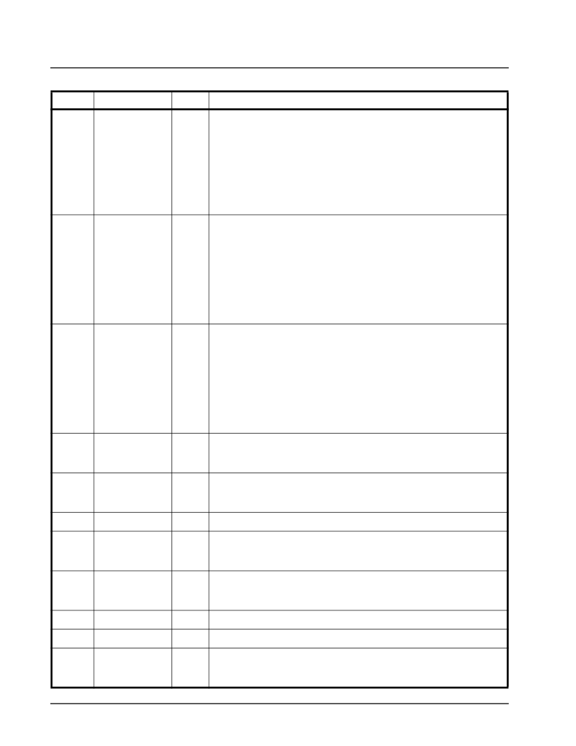
PIN DESCRIPTION
P
IN
#
S
IGNAL
N
AME
T
YPE
D
ESCRIPTION
相關PDF資料 |
PDF描述 |
|---|---|
| XRT73L03A | 3 CHANNEL DS3/E3/STS-1 LINE INTERFACE UNIT |
| XRT73L03AIV | 3 CHANNEL DS3/E3/STS-1 LINE INTERFACE UNIT |
| XRT73L03B | 3 CHANNEL DS3/E3/STS-1 LINE INTERFACE UNIT |
| XRT73L03BIV | 3 CHANNEL DS3/E3/STS-1 LINE INTERFACE UNIT |
| XRT73L04A | 4 CHANNEL DS3/E3/STS-1 LINE INTERFACE UNIT |
相關代理商/技術參數(shù) |
參數(shù)描述 |
|---|---|
| XRT73L02M | 制造商:EXAR 制造商全稱:EXAR 功能描述:TWO CHANNEL E3/DS3/STS-1 LINE INTERFACE UNIT |
| XRT73L02MES | 功能描述:網(wǎng)絡控制器與處理器 IC RoHS:否 制造商:Micrel 產(chǎn)品:Controller Area Network (CAN) 收發(fā)器數(shù)量: 數(shù)據(jù)速率: 電源電流(最大值):595 mA 最大工作溫度:+ 85 C 安裝風格:SMD/SMT 封裝 / 箱體:PBGA-400 封裝:Tray |
| XRT73L02MIV | 制造商:EXAR 制造商全稱:EXAR 功能描述:TWO CHANNEL E3/DS3/STS-1 LINE INTERFACE UNIT |
| XRT73L02MIV-F | 功能描述:外圍驅(qū)動器與原件 - PCI RoHS:否 制造商:PLX Technology 工作電源電壓: 最大工作溫度: 安裝風格:SMD/SMT 封裝 / 箱體:FCBGA-1156 封裝:Tray |
| XRT73L02MIVTR-F | 功能描述:網(wǎng)絡控制器與處理器 IC RoHS:否 制造商:Micrel 產(chǎn)品:Controller Area Network (CAN) 收發(fā)器數(shù)量: 數(shù)據(jù)速率: 電源電流(最大值):595 mA 最大工作溫度:+ 85 C 安裝風格:SMD/SMT 封裝 / 箱體:PBGA-400 封裝:Tray |
發(fā)布緊急采購,3分鐘左右您將得到回復。