- 您現(xiàn)在的位置:買賣IC網(wǎng) > PDF目錄383644 > MT90221 (Mitel Networks Corporation) Quad IMA/UNI PHY Device(四端口 IMA/UNI 物理層設(shè)備(四端口ATM IMA和UNI處理器)) PDF資料下載
參數(shù)資料
| 型號(hào): | MT90221 |
| 廠商: | Mitel Networks Corporation |
| 英文描述: | Quad IMA/UNI PHY Device(四端口 IMA/UNI 物理層設(shè)備(四端口ATM IMA和UNI處理器)) |
| 中文描述: | 四IMA的/單向物理層設(shè)備(IMA的四端口/單向物理層設(shè)備(四端口自動(dòng)柜員機(jī)IMA的和單向處理器)) |
| 文件頁數(shù): | 41/116頁 |
| 文件大小: | 309K |
| 代理商: | MT90221 |
第1頁第2頁第3頁第4頁第5頁第6頁第7頁第8頁第9頁第10頁第11頁第12頁第13頁第14頁第15頁第16頁第17頁第18頁第19頁第20頁第21頁第22頁第23頁第24頁第25頁第26頁第27頁第28頁第29頁第30頁第31頁第32頁第33頁第34頁第35頁第36頁第37頁第38頁第39頁第40頁當(dāng)前第41頁第42頁第43頁第44頁第45頁第46頁第47頁第48頁第49頁第50頁第51頁第52頁第53頁第54頁第55頁第56頁第57頁第58頁第59頁第60頁第61頁第62頁第63頁第64頁第65頁第66頁第67頁第68頁第69頁第70頁第71頁第72頁第73頁第74頁第75頁第76頁第77頁第78頁第79頁第80頁第81頁第82頁第83頁第84頁第85頁第86頁第87頁第88頁第89頁第90頁第91頁第92頁第93頁第94頁第95頁第96頁第97頁第98頁第99頁第100頁第101頁第102頁第103頁第104頁第105頁第106頁第107頁第108頁第109頁第110頁第111頁第112頁第113頁第114頁第115頁第116頁
MT90221
33
6.0 Support Blocks
6.1
The MT90221 includes 64 24-bit counters to provide
statistical information on the device’s operation. All
the counters are cleared by a hardware reset. A
maskable interrupt can be generated when the
counter overflows.
Counter Block
A predetermined value can also be loaded in a
counter. This feature can be used to generate an
interrupt after a specified number of cells is
processed. Counter values are incremented by 1 for
every event occurrence and, when the count goes to
all 1’s, will overflow (to all 0’s).
6.1.1
There are four counters associated with the each of
the 8 UTOPIA Inputs (from ATM layer to the
MT90221) for a total of 32 counters. These counters
record the following information:
the total number of cells received at the
UTOPIA Input I/F
the total number of Idle Cells received at the
UTOPIA Input I/F, removed or not
the total number of Unassigned Cells received
at the UTOPIA Input I/F, removed or not
the number of cells having a single or multiple
bit error in the HEC, removed or not but not
including the cells where the HEC is corrected
UTOPIA Input I/F counters
6.1.2
There are four counters associated with the each of
the four transmit PCM links for a total of 16 Transmit
counters. These counters record the following
information and are active as soon as the RX PCM
port is enabled:
the total number of cells sent through the PCM
link
the total number of Idle/Filler cells sent through
the PCM link, with good or bad HEC
the total number of Stuff cells sent through the
PCM link
Transmit PCM I/F Counters
the total number of ICP cells sent through the
PCM link
6.1.3
There are four counters associated with each of the
four receive PCM links for a total of 16 Receive
counters. These counters record the following
information:
the total number of cells received through the
PCM link or total number of Stuff events
received on the link (option selected in
RX Link
Control
registers)
the total number of Idle/Filler cells received
through the PCM link
the total number of ICP Cells with violation
received through the PCM link
the total number of cells with wrong HEC
received through the PCM link but not including
the cells where the HEC is corrected
Receive PCM I/F Counters
6.1.4
Accessing (READ) counters is a three step function.
First, the desired counter must be selected by writing
to the
Counter Select Register
. Second, the READ
command (’0x00x101’) is written to the
Counter
Transfer Command
register. This command causes
the current three byte count value to be copied from
the specified counter to the three byte-wide
Counter
Bytes
registers (note that this value is unchanged
until another counter read command is issued). And
third, the
Counter Bytes
registers are read to obtain
the three byte count value of the selected counter.
Access to the Counters
Pre-loading (WRITE) a counter is also a three step
function. First, the three byte, pre-load value, is
written to the three byte-wide
Counter Bytes
registers. Second, the identification of the counter to
be pre-loaded is written to the
Counter Select
Register
.
And
third,
(’0x00x001’) is written to the
Counter transfer
Command
register.
the
WRITE
command
The IRQ enable bit of a counter is set, or reset, by
selecting the counter and writing to the appropriate
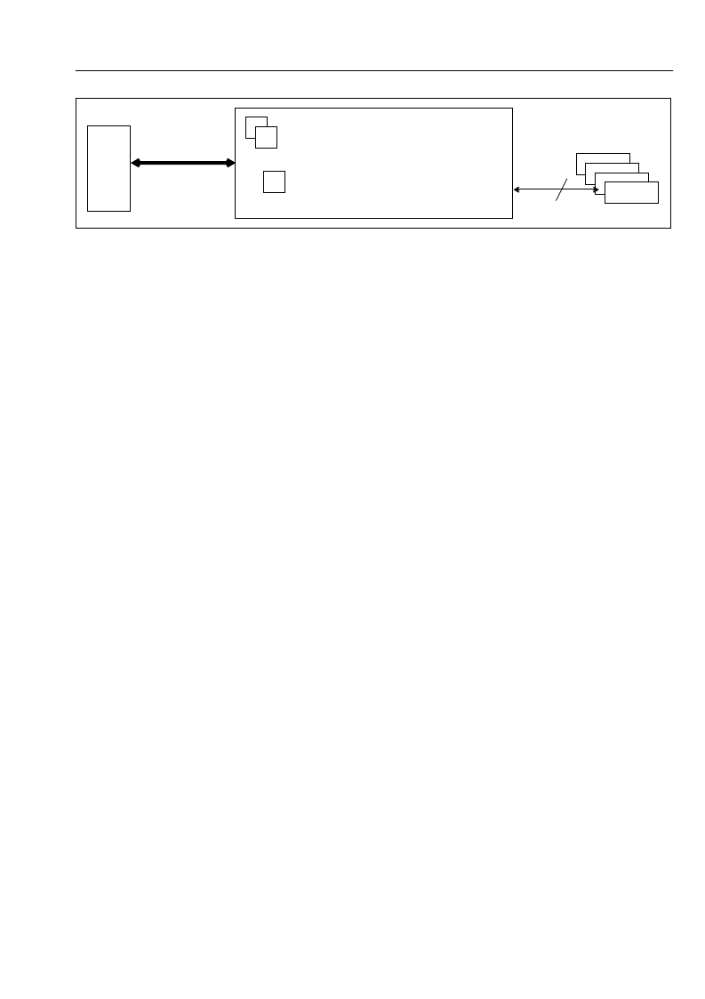
Figure 17 - ATM Mixed-Mode Interface to One MT90221
(IMA Group #1)
(2 Links in UNI Mode)
ATM
Layer
Device
2 UTOPIA Ports
(UNI)
4
Framer
1 UTOPIA Port
(2 links)
相關(guān)PDF資料 |
PDF描述 |
|---|---|
| MT90401 | SONET/SDH System Synchronizer(SONET/SDH 系統(tǒng)同步裝置(由一個(gè)數(shù)字鎖相環(huán)組成)) |
| MT9040 | T1/E1 Synchronizer(T1/E1 系統(tǒng)同步裝置(由一個(gè)數(shù)字鎖相環(huán)組成)) |
| MT9041A | () |
| MT9041B | T1/E1 System Synchronizer(T1/E1系統(tǒng)同步裝置(由一個(gè)數(shù)字鎖相環(huán)組成)) |
| MT9042B | () |
相關(guān)代理商/技術(shù)參數(shù) |
參數(shù)描述 |
|---|---|
| MT90221AL | 制造商:MITEL 制造商全稱:Mitel Networks Corporation 功能描述:Quad IMA/UNI PHY Device |
| MT90222 | 制造商:ZARLINK 制造商全稱:Zarlink Semiconductor Inc 功能描述:4/8/16 Port IMA/TC PHY Device |
| MT90222AG | 制造商:Microsemi Corporation 功能描述:ATM IMA 40MBPS 2.5V 384BGA - Trays |
| MT90222AG2 | 制造商:Microsemi Corporation 功能描述:ATM IMA 40MBPS 2.5V 384BGA /BAKE/DRYPACK - Trays |
| MT90223AG | 制造商:Microsemi Corporation 功能描述:ATM IMA 80MBPS 2.5V 384BGA - Trays |
發(fā)布緊急采購,3分鐘左右您將得到回復(fù)。