- 您現(xiàn)在的位置:買賣IC網(wǎng) > PDF目錄67684 > IBM37RGB524CF17A 1600 X 1280 PIXELS PALETTE-DAC DSPL CTLR, PQFP144 PDF資料下載
參數(shù)資料
| 型號(hào): | IBM37RGB524CF17A |
| 元件分類: | 顯示控制器 |
| 英文描述: | 1600 X 1280 PIXELS PALETTE-DAC DSPL CTLR, PQFP144 |
| 封裝: | QFP-144 |
| 文件頁(yè)數(shù): | 53/72頁(yè) |
| 文件大?。?/td> | 509K |
| 代理商: | IBM37RGB524CF17A |
第1頁(yè)第2頁(yè)第3頁(yè)第4頁(yè)第5頁(yè)第6頁(yè)第7頁(yè)第8頁(yè)第9頁(yè)第10頁(yè)第11頁(yè)第12頁(yè)第13頁(yè)第14頁(yè)第15頁(yè)第16頁(yè)第17頁(yè)第18頁(yè)第19頁(yè)第20頁(yè)第21頁(yè)第22頁(yè)第23頁(yè)第24頁(yè)第25頁(yè)第26頁(yè)第27頁(yè)第28頁(yè)第29頁(yè)第30頁(yè)第31頁(yè)第32頁(yè)第33頁(yè)第34頁(yè)第35頁(yè)第36頁(yè)第37頁(yè)第38頁(yè)第39頁(yè)第40頁(yè)第41頁(yè)第42頁(yè)第43頁(yè)第44頁(yè)第45頁(yè)第46頁(yè)第47頁(yè)第48頁(yè)第49頁(yè)第50頁(yè)第51頁(yè)第52頁(yè)當(dāng)前第53頁(yè)第54頁(yè)第55頁(yè)第56頁(yè)第57頁(yè)第58頁(yè)第59頁(yè)第60頁(yè)第61頁(yè)第62頁(yè)第63頁(yè)第64頁(yè)第65頁(yè)第66頁(yè)第67頁(yè)第68頁(yè)第69頁(yè)第70頁(yè)第71頁(yè)第72頁(yè)
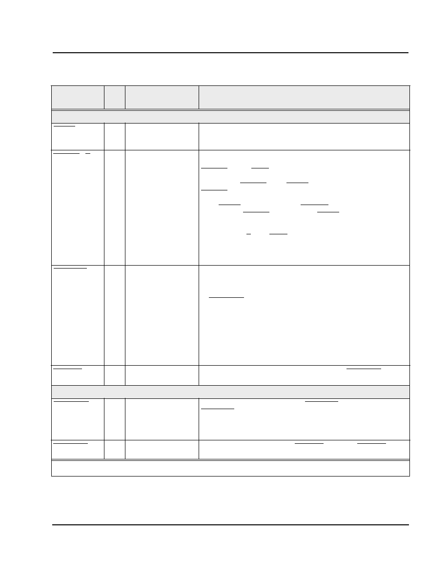
March 17, 1995
51
IBM
RGB524
Video Control Inputs
BLANK
I
78
A low level indicates blanking time; a high level indicates active picture time
(pixel data, cursor, or border displayed).
Latched on rising edge of LCLK.
BORDER/OE
I
79
This is a shared input. It may be used either as a border indicator, or as
an interlace control. Within this document, this input may be referred to as
BORDER or ODD/EVEN, depending on usage.
When used as BORDER: When BLANK is high (picture time), a low level on
BORDER indicates the contents of the border registers should be displayed,
and a high level indicates that pixel data or cursor should be displayed.
When BLANK is low (blanking time) BORDER must be low. If no border is
to be displayed BORDER should be tied to BLANK.
Latched on rising edge of LCLK.
When used as O/E (ODD/EVEN): Used in interlace mode to identify a eld
as odd or even; determines which row of cursor RAM to display if the cursor
is enabled.
In this usage the input should only change during vertical blanking.
HCSYNCIN
I
77
This is a shared input. It may be used either as horizontal sync in or
composite sync in.
When used as Horizontal Sync In, a delayed copy of this signal is presented
on HSYNCOUT to align the timing of horizontal sync to the pixel data at the
DACs. The incoming polarity can be inverted under register control.
Latched on rising edge of LCLK.
When used as Composite Sync In, when enabled, this signal is presented on
the Green DAC with the video data. The signal is delayed to match the delay
of the pixel data. The incoming polarity can be inverted under register
control.
Latched on rising edge of LCLK
VSYNCIN
I
76
Vertical Sync In. A copy of this signal is presented on VSYNCOUT. The
incoming polarity can be inverted under register control.
Video Control Outputs
HSYNCOUT
O
32
Horizontal Sync Out. This is a copy of HCSYNCIN (or inverted
HCSYNCIN), delayed by the same number of pixel clocks as seen by the
pixel data at the input to the DACs. It can be forced to a high or low level or
3-stated under register control. The amount of delay may also be adjusted
with the Horizontal Sync Position register.
VSYNCOUT
O
12
Vertical Sync Out. This is a copy of VSYNCIN (or inverted VSYNCIN). It can
be forced to a high or low level or 3-stated under register control.
Table 10. Pin Descriptions (Continued)
Signal
Typ
e
Pin(s)
Description
Type: I = Input, O = Output, B = Bidirectional, C = Component
相關(guān)PDF資料 |
PDF描述 |
|---|---|
| IC-WT-SO16N | ROTARY/LINEAR OPTICAL POSITION ENCODER |
| ICD2028SCR-5 | 100 MHz, PROC SPECIFIC CLOCK GENERATOR, PDSO20 |
| ICD2063SC-1 | 135 MHz, VIDEO CLOCK GENERATOR, PDSO16 |
| ICD2063SC-2 | 135 MHz, VIDEO CLOCK GENERATOR, PDSO16 |
| ICD2063SC-3 | 135 MHz, VIDEO CLOCK GENERATOR, PDSO16 |
相關(guān)代理商/技術(shù)參數(shù) |
參數(shù)描述 |
|---|---|
| IBM37RGB524CF22A | 制造商:未知廠家 制造商全稱:未知廠家 功能描述:Video DAC with Color Palette (RAMDAC) |
| IBM39ENV422DLL00C | 制造商:IBM 功能描述: |
| IBM39ENV422PBA17C | 制造商:IBM Microelectronics 功能描述:VID ENCODER 420PIN HPBGA - Trays 制造商:IBM 功能描述:IBM IBM39ENV422PBA17C Encoders - Decoders |
| IBM39MPEGCD20PFD22C | 制造商:IBM 功能描述: |
| IBM39MPEGCS22PFJ22C | 制造商:IBM 功能描述: |
發(fā)布緊急采購(gòu),3分鐘左右您將得到回復(fù)。