- 您現(xiàn)在的位置:買(mǎi)賣(mài)IC網(wǎng) > PDF目錄382949 > EM6517 (Electronic Theatre Controls, Inc.) 4-BIT SINGLE-CHIP MICROCONTROLLER FOR SMALL GENERAL-PURPOSE INFRARED REMOTE CONTROL TRANSMITTER PDF資料下載
參數(shù)資料
| 型號(hào): | EM6517 |
| 廠商: | Electronic Theatre Controls, Inc. |
| 元件分類: | 4位微控制器 |
| 英文描述: | 4-BIT SINGLE-CHIP MICROCONTROLLER FOR SMALL GENERAL-PURPOSE INFRARED REMOTE CONTROL TRANSMITTER |
| 中文描述: | 4位單片機(jī)的小型通用紅外遙控器 |
| 文件頁(yè)數(shù): | 6/66頁(yè) |
| 文件大小: | 762K |
| 代理商: | EM6517 |
第1頁(yè)第2頁(yè)第3頁(yè)第4頁(yè)第5頁(yè)當(dāng)前第6頁(yè)第7頁(yè)第8頁(yè)第9頁(yè)第10頁(yè)第11頁(yè)第12頁(yè)第13頁(yè)第14頁(yè)第15頁(yè)第16頁(yè)第17頁(yè)第18頁(yè)第19頁(yè)第20頁(yè)第21頁(yè)第22頁(yè)第23頁(yè)第24頁(yè)第25頁(yè)第26頁(yè)第27頁(yè)第28頁(yè)第29頁(yè)第30頁(yè)第31頁(yè)第32頁(yè)第33頁(yè)第34頁(yè)第35頁(yè)第36頁(yè)第37頁(yè)第38頁(yè)第39頁(yè)第40頁(yè)第41頁(yè)第42頁(yè)第43頁(yè)第44頁(yè)第45頁(yè)第46頁(yè)第47頁(yè)第48頁(yè)第49頁(yè)第50頁(yè)第51頁(yè)第52頁(yè)第53頁(yè)第54頁(yè)第55頁(yè)第56頁(yè)第57頁(yè)第58頁(yè)第59頁(yè)第60頁(yè)第61頁(yè)第62頁(yè)第63頁(yè)第64頁(yè)第65頁(yè)第66頁(yè)
EM6517
FOR ENGINEERING ONLY
EM Microelectronic-Marin SA, 09/99, Rev. A/277
6
3
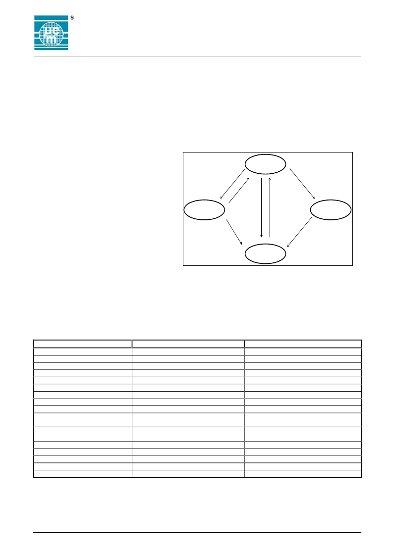
The EM6517-1 has two low power dissipation modes, standby and sleep. Figure 5 is a transition diagram for
these modes.
Operating Modes
3.1 Active Mode
The active mode is the actual CPU running mode. Instructions are read from the internal ROM and executed by
the CPU. Leaving active mode via the halt instruction to go into standby mode, the
Sleep
bit write to go into
Sleep mode or a reset from port A to go into reset mode.
3.2 Standby Mode
Executing a halt instruction puts the
EM6517-1 into standby mode. The voltage
regulator, oscillator, watchdog timer, ADC,
interrupts, SWB, timers and counters are
operating. However, the CPU stops since the
clock related to instruction execution stops.
Registers, RAM and I/O pins retain their
states prior to standby mode. A reset or an
interrupt request if enabled cancels standby.
3.3 Sleep Mode
Writing to the
Sleep
bit in the
RegSysCntl1
register puts the EM6517-1 in sleep mode.
The oscillator stops and most functions of
the EM6517-1 are inactive. To be able to
write to the
Sleep
bit, the
SleepEn
bit in
RegSysCntl2
must first be set to "1". In
sleep mode only the voltage regulator and the reset input are active. The RAM data integrity is maintained.
Sleep mode may be canceled only by a high level of min 10μs at the Reset terminal or by the selected port A
input reset combination, if option
InpResSleep
in register
OPTFSelPB
is turned on.
Due to the cold-start characteristics of the oscillator, waking up from sleep mode may take some time to
guarantee stable oscillation. During sleep mode and the following start up the EM6517-1 is in reset state.
Waking up from sleep clears the
Sleep
flag but not the
SleepEn
bit. Inspecting the
SleepEn
allows to
determine if the EM6517-1 was powered up (
SleepEn
= "0") or woken up from sleep (
SleepEn
= "1").
Table 3.3.1. Internal State in Standby and Sleep Mode
Function
Oscillator
Oscillator Watchdog
Instruction Execution
Interrupt Functions
Registers and Flags
RAM Data
Option Registers
Timer & Counter
Logic Watchdog
I/O Port B and Serial Port
Standby
Active
Active
Stopped
Active
Retained
Retained
Retained
Active
Active
Active
Sleep
Stopped
Stopped
Stopped
Stopped
Reset
Retained
Retained
Reset
Reset
High Impedance,
Pull’s as defined in option register
No pull-downs and inputs deactivated
except if
InpResSleep
= "1"
Stopped (display off)
Active
High Impedance
Stopped
Active
Input Port A
Active
LCD
Active
Active
Active
Strobe Output
Buzzer Output
Voltage Level Detector
Reset Pin
Finishes ongoing measure, then stop
Active
Figure 5. Mode transition diagram
Active
Halt
instruction
Sleep bit
write
IRQ
Standby
Sleep
Reset=1
Reset=0
Reset=1
Reset=1
Reset
相關(guān)PDF資料 |
PDF描述 |
|---|---|
| emg6 | General purpose (dual digital transistors) |
| EMG6 | General purpose (dual digital transistors) |
| EMX-303L1 | Magnetic transducer Buzzer |
| EMX-303L2 | Magnetic transducer Buzzer |
| EMX-303P2 | Magnetic transducer Buzzer |
相關(guān)代理商/技術(shù)參數(shù) |
參數(shù)描述 |
|---|---|
| EM6517-240# | 制造商:DANAHER - FLUKE 功能描述:BNC TO BANTAM CABLE 制造商:Fluke Electronics 功能描述:BNC TO BANTAM CABLE |
| EM6520 | 制造商:EMMICRO 制造商全稱:EM Microelectronic - MARIN SA 功能描述:MFP version of EM6620 Ultra Low Power Microcontroller 4x8 LCD Driver |
| EM6521 | 制造商:未知廠家 制造商全稱:未知廠家 功能描述:4 bit Microcontroller |
| EM6522 | 制造商:EMMICRO 制造商全稱:EM Microelectronic - MARIN SA 功能描述:This board contains the different MFP’s |
| EM65240 | 制造商:未知廠家 制造商全稱:未知廠家 功能描述:Graphic STN LCD Drivers |
發(fā)布緊急采購(gòu),3分鐘左右您將得到回復(fù)。