- 您現(xiàn)在的位置:買賣IC網(wǎng) > PDF目錄359354 > VDP3108 (MICRONAS SEMICONDUCTOR HOLDING AG) Single-Chip Video Processor PDF資料下載
參數(shù)資料
| 型號: | VDP3108 |
| 廠商: | MICRONAS SEMICONDUCTOR HOLDING AG |
| 英文描述: | Single-Chip Video Processor |
| 中文描述: | 單芯片視頻處理器 |
| 文件頁數(shù): | 31/61頁 |
| 文件大小: | 2638K |
| 代理商: | VDP3108 |
第1頁第2頁第3頁第4頁第5頁第6頁第7頁第8頁第9頁第10頁第11頁第12頁第13頁第14頁第15頁第16頁第17頁第18頁第19頁第20頁第21頁第22頁第23頁第24頁第25頁第26頁第27頁第28頁第29頁第30頁當(dāng)前第31頁第32頁第33頁第34頁第35頁第36頁第37頁第38頁第39頁第40頁第41頁第42頁第43頁第44頁第45頁第46頁第47頁第48頁第49頁第50頁第51頁第52頁第53頁第54頁第55頁第56頁第57頁第58頁第59頁第60頁第61頁
ADVANCE INFORMATION
VDP 3108
MICRONAS INTERMETALL
31
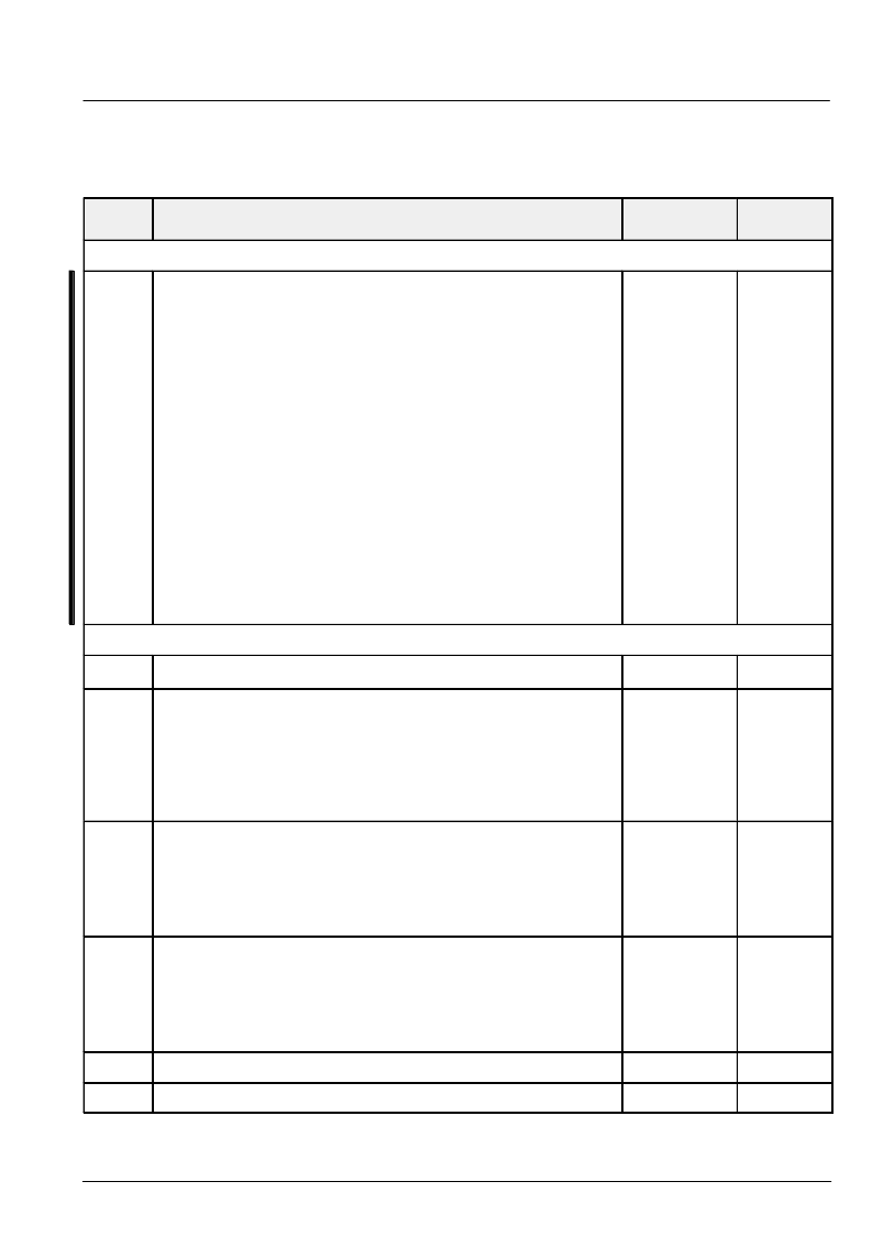
Table 3–2: Control Registers of the Fast Processor
– default values are initialized at reset
– * indicates that register is initialized according to the current standard when SDT register is changed.
FP Sub
address
Function
Default
Name
Standard Selection
h’1b
Standard select:
0
1
2
3
4
5
6
7
PAL B,G,H,I
NTSC M
SECAM
NTSC44
PAL M
PAL N
PAL 60
NTSC COMB
(50 Hz)
(60 Hz)
(50 Hz)
(60 Hz)
(60 Hz)
(50 Hz)
(60 Hz)
(60 Hz)
4.433618
3.579545
4.286
4.433618
3.575611
3.582056
4.433618
3.579545
The activated routine will set up several blocks for the selected standard.
Option bits:
(OR for the new selected standard)
h’100
no hpll setup
h’200
no vertical setup
h’400
no acc setup
Note: After FP has switched to a new standard, the MSB of SDT is set
to 1 to indicate operation complete.
0
SDT
Color Processing
h’1c
NTSC tint angle,
512 =
π
/4
0
TINT
h’a0
ACC reference level to adjust C
r
, C
b
levels on picture bus.
(use main matrix)
ACCREF = 0: ACC function is disabled, chroma gain can be adjusted
via ACCb / ACCr register
ACC reference level for increased color saturation.
(use side matrix)
P/N: 2070*
S: 0*
P/N: 2263
ACCREF
h’a3
ACC multiplier value for SECAM Dr chroma component to adjust C
r
level
on picture bus. (use main matrix)
b[10:0]
eeemmmmmmmmm * 2^–e
ACC multiplier value for SECAM Dr chroma component for increased
color saturation (use side matrix)
S: 1496*
S:1532
ACCr
h’a4
ACC multiplier value for SECAM Db chroma component to adjust C
b
lev-
el on picture bus. (use main matrix)
b[10:0]
eeemmmmmmmmm * 2^–e
ACC multiplier value for SECAM Dr chroma component for increased
color saturation (use side matrix)
S: 1155*
S: 1177
ACCb
h’a8
amplitude color killer level (0:killer disabled)
30
KILVL
h’a9
amplitude color killer hysteresis
10
KILHY
相關(guān)PDF資料 |
PDF描述 |
|---|---|
| VDP3130Y | Video Processor Family |
| VDP31XXB | Video Processor Family |
| VDP3108PR | Consumer IC |
| VDSGLD_38.88 | TRANS PREBIASED PNP 200MW SOT23 |
| VDSL5100I | TVS 400W 43V UNIDIRECT SMA |
相關(guān)代理商/技術(shù)參數(shù) |
參數(shù)描述 |
|---|---|
| VDP3108B | 制造商:MICRONAS 制造商全稱:MICRONAS 功能描述:Video Processor Family |
| VDP3108PR | 制造商:未知廠家 制造商全稱:未知廠家 功能描述:Consumer IC |
| VDP3112B | 制造商:MICRONAS 制造商全稱:MICRONAS 功能描述:Video Processor Family |
| VDP3116B | 制造商:MICRONAS 制造商全稱:MICRONAS 功能描述:Video Processor Family |
| VDP3120B | 制造商:MICRONAS 制造商全稱:MICRONAS 功能描述:Video Processor Family |
發(fā)布緊急采購,3分鐘左右您將得到回復(fù)。