- 您現(xiàn)在的位置:買賣IC網(wǎng) > PDF目錄359354 > VDP3108 (MICRONAS SEMICONDUCTOR HOLDING AG) Single-Chip Video Processor PDF資料下載
參數(shù)資料
| 型號(hào): | VDP3108 |
| 廠商: | MICRONAS SEMICONDUCTOR HOLDING AG |
| 英文描述: | Single-Chip Video Processor |
| 中文描述: | 單芯片視頻處理器 |
| 文件頁(yè)數(shù): | 27/61頁(yè) |
| 文件大小: | 2638K |
| 代理商: | VDP3108 |
第1頁(yè)第2頁(yè)第3頁(yè)第4頁(yè)第5頁(yè)第6頁(yè)第7頁(yè)第8頁(yè)第9頁(yè)第10頁(yè)第11頁(yè)第12頁(yè)第13頁(yè)第14頁(yè)第15頁(yè)第16頁(yè)第17頁(yè)第18頁(yè)第19頁(yè)第20頁(yè)第21頁(yè)第22頁(yè)第23頁(yè)第24頁(yè)第25頁(yè)第26頁(yè)當(dāng)前第27頁(yè)第28頁(yè)第29頁(yè)第30頁(yè)第31頁(yè)第32頁(yè)第33頁(yè)第34頁(yè)第35頁(yè)第36頁(yè)第37頁(yè)第38頁(yè)第39頁(yè)第40頁(yè)第41頁(yè)第42頁(yè)第43頁(yè)第44頁(yè)第45頁(yè)第46頁(yè)第47頁(yè)第48頁(yè)第49頁(yè)第50頁(yè)第51頁(yè)第52頁(yè)第53頁(yè)第54頁(yè)第55頁(yè)第56頁(yè)第57頁(yè)第58頁(yè)第59頁(yè)第60頁(yè)第61頁(yè)

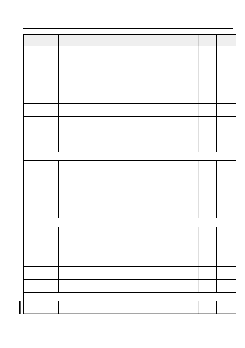
ADVANCE INFORMATION
VDP 3108
MICRONAS INTERMETALL
27
Name
Default
Function
Mode
Number
of bits
I
2
C Sub
address
69
9
w v
luma peaking filter, the gain at high frequencies and small signal
amplitudes is: 1 + (k1+k2)/8
bit [3:0]
0..15
k1: peaking level undershoot
bit [7:4]
0..15
k2: peaking level overshoot
4
4
PKUN
PKOV
6d
9
w v
luma peaking filter, coring
bit [5:0]
0..31
bit[7:6]
bit[8]
0/1
coring level
reserved
peaking filter CF 2.5/3.2 MHz
1
0
COR
PFS
4d
9
w v
luma soft limiter
bit[7:0]
0..255
maximum limit for low frequency comp.
255
SLDC
49
9
w v
luma soft limiter
bit[7:0]
0..255
maximum limit for output signal
255
SLO
41
9
w v
luma soft limiter
bit[4:0]
bit[5]
0..31
0/1
loop filter gain
enable/disable noise reduction
SFG
DNO
45
9
w v
luma soft limiter
bit[4:0]
bit[5]
0..31
0/1
notch filter gain (for manual notch)
automatic/manual notch
SFGM
SLM
DISPLAY PROCESSOR – CHROMA
14
8
w/r v
luma / chroma matching delay
bit [2:0]
–2...2
bit [3]
0/1
variable chroma delay
chroma polarity signed/offset binary
0
1
LDB
COB
72
9
w v
digital transient improvement
bit [4:0]
0..31
bit [8:5]
0..15
transient gain Cr
coring level for Cr, Cb
31
3
CPKV
CCOR
7a
9
w v
digital transient improvement
bit [4:0]
0..31
bit [7:5]
bit [8]
0/1
transient gain Cb
reserved
filter characteristic broad/narrow
31
1
CPKU
CFS
DISPLAY PROCESSOR – MATRIX
7c/74
9
w v
main picture matrix coefficient R–Y = MR1M*Cb + MR2M*Cr
bit[9:0]
–256 ... 255/128
0
86
MR1M,
MR2M
6c/64
9
w v
main picture matrix coefficient G–Y = MG1M*Cb + MG2M*Cr
bit[9:0]
–256 ... 255/128
–22
–44
MG1M,
MG2M
5c/54
9
w v
main picture matrix coefficient B–Y = MB1M*Cb + MB2M*Cr
bit[9:0]
–256 ... 255 /128
113
0
MB1M,
MB2M
78/70
9
w v
side picture matrix coefficient R–Y = MR1S*Cb + MR2S*Cr
bit[9:0]
–256 ... 255/128
0
73
MR1S,
MR2S
68/60
9
w v
side picture matrix coefficient G–Y = MG1S*Cb + MG2S*Cr
bit[9:0]
–256 ... 255/128
–19
–37
MG1S,
MG2S
DISPLAY PROCESSOR – COLOR LOOK-UP TABLE
58/50
9
w v
side picture matrix coefficient B–Y = MB1S*Cb+ MB2S*Cr
bit[9:0]
–256 ... 255/128
97
0
MB1S,
MB2S
相關(guān)PDF資料 |
PDF描述 |
|---|---|
| VDP3130Y | Video Processor Family |
| VDP31XXB | Video Processor Family |
| VDP3108PR | Consumer IC |
| VDSGLD_38.88 | TRANS PREBIASED PNP 200MW SOT23 |
| VDSL5100I | TVS 400W 43V UNIDIRECT SMA |
相關(guān)代理商/技術(shù)參數(shù) |
參數(shù)描述 |
|---|---|
| VDP3108B | 制造商:MICRONAS 制造商全稱:MICRONAS 功能描述:Video Processor Family |
| VDP3108PR | 制造商:未知廠家 制造商全稱:未知廠家 功能描述:Consumer IC |
| VDP3112B | 制造商:MICRONAS 制造商全稱:MICRONAS 功能描述:Video Processor Family |
| VDP3116B | 制造商:MICRONAS 制造商全稱:MICRONAS 功能描述:Video Processor Family |
| VDP3120B | 制造商:MICRONAS 制造商全稱:MICRONAS 功能描述:Video Processor Family |
發(fā)布緊急采購(gòu),3分鐘左右您將得到回復(fù)。