- 您現(xiàn)在的位置:買賣IC網(wǎng) > PDF目錄98303 > TSC2302IRGZRG4 (TEXAS INSTRUMENTS INC) SPECIALTY CONSUMER CIRCUIT, PQCC48 PDF資料下載
參數(shù)資料
| 型號(hào): | TSC2302IRGZRG4 |
| 廠商: | TEXAS INSTRUMENTS INC |
| 元件分類: | 消費(fèi)家電 |
| 英文描述: | SPECIALTY CONSUMER CIRCUIT, PQCC48 |
| 封裝: | GREEN, PLASTIC, VQFN-48 |
| 文件頁數(shù): | 41/85頁 |
| 文件大小: | 1483K |
| 代理商: | TSC2302IRGZRG4 |
第1頁第2頁第3頁第4頁第5頁第6頁第7頁第8頁第9頁第10頁第11頁第12頁第13頁第14頁第15頁第16頁第17頁第18頁第19頁第20頁第21頁第22頁第23頁第24頁第25頁第26頁第27頁第28頁第29頁第30頁第31頁第32頁第33頁第34頁第35頁第36頁第37頁第38頁第39頁第40頁當(dāng)前第41頁第42頁第43頁第44頁第45頁第46頁第47頁第48頁第49頁第50頁第51頁第52頁第53頁第54頁第55頁第56頁第57頁第58頁第59頁第60頁第61頁第62頁第63頁第64頁第65頁第66頁第67頁第68頁第69頁第70頁第71頁第72頁第73頁第74頁第75頁第76頁第77頁第78頁第79頁第80頁第81頁第82頁第83頁第84頁第85頁
www.ti.com
X+
MUX
A/D
Converter
Temperature Select
TEMP1
TEMP2
°K +
q DV
k n(N)
(7)
DV + V I82 –V I1
(8)
°K +
q DV
k n(N)
(9)
TSC2302
SLAS394 – JULY 2003
OPERATION - TEMPERATURE MEASUREMENT
In some applications, such as estimating remaining battery life or setting RAM refresh rate, a measurement of
ambient temperature is required. The temperature measurement technique used in the TSC2302 relies on the
characteristics of a semiconductor junction operating at a fixed current level. The forward diode voltage (VBE) has
a well-defined characteristic versus temperature. The ambient temperature can be predicted in applications by
knowing the 25
°C value of the V
BE voltage and then monitoring the delta of that voltage as the temperature
changes.
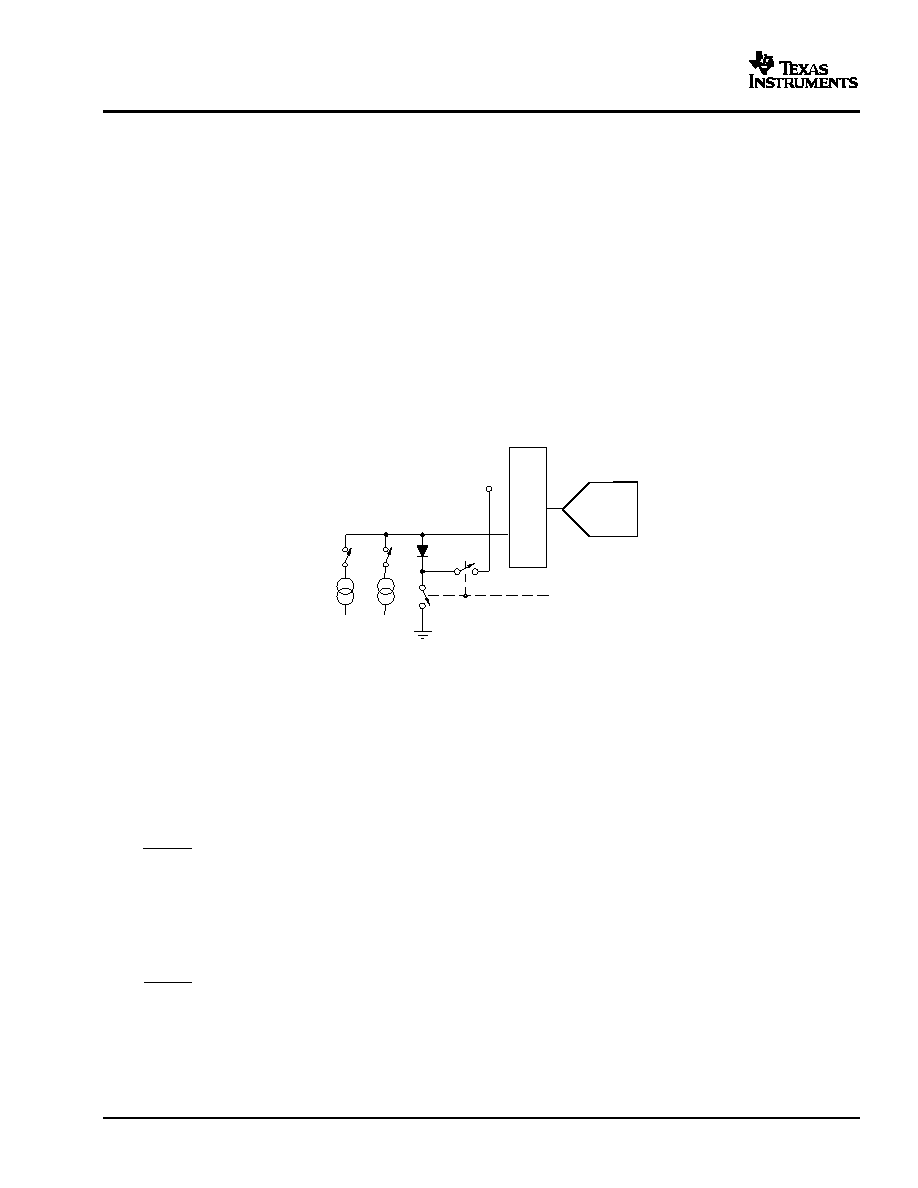
The TSC2302 offers two modes of temperature measurement. The first mode requires calibration at a known
temperature, but only requires a single reading to predict the ambient temperature. A diode, as shown in Figure
56, is used during this measurement cycle. The voltage across this diode is typically 600 mV at 25
°C while
conducting a 20-A current. The absolute value of this diode voltage can vary several millivolts, but the
temperature coefficient (TC) of this voltage is very consistent at -2.1 mV/
°C. During the final test of the end
product, the diode voltage would be measured by the TSC2302 ADC at a known room temperature, and the
corresponding digital code stored in system memory, for calibration purposes by the user. The result is an
equivalent temperature measurement resolution of 0.3
°C/LSB. This measurement of what is referred to as
Temperature 1 is illustrated in Figure 57.
Figure 56. Functional Block Diagram of Temperature Measurement Mode
The second mode does not require a test temperature calibration, but uses a two-measurement (differential)
method to eliminate the need for absolute temperature calibration, and achieves a 2
°C/LSB accuracy. This mode
requires a second conversion with a current 82 times larger than the first 20uA current. The voltage difference
between the first (TEMP1) and second (Temp2) conversion, using 82 times the bias current, is represented by
kT/q ln (N), where N is the current ratio = 82, k = Boltzmann’s constant (1.38054 x 10⁻²³ electron volts/degree
Kelvin), q = the electron charge (1.602189 x 10⁻¹⁹ C), and T = the temperature in degrees Kelvin. This method
can provide much improved absolute temperature measurement without calibration, with resolution of 2
°C/LSB.
The resultant equation for solving for
°K is:
where:
(in mV)
Temperature 2 measurement is illustrated in Figure 58.
46
相關(guān)PDF資料 |
PDF描述 |
|---|---|
| TSDC4872IJT | 1 W, 1 CHANNEL, AUDIO AMPLIFIER, PBGA8 |
| TS4872IJT | 1 W, 1 CHANNEL, AUDIO AMPLIFIER, PBGA8 |
| TSH103ID | 3 CHANNEL, VIDEO AMPLIFIER, PDSO8 |
| TSH103IDT | 3 CHANNEL, VIDEO AMPLIFIER, PDSO8 |
| TSH120ICT | SPECIALTY CONSUMER CIRCUIT, PDSO6 |
相關(guān)代理商/技術(shù)參數(shù) |
參數(shù)描述 |
|---|---|
| TSC2303IZQZ | 制造商:Texas Instruments 功能描述: |
| TSC2303IZQZR | 制造商:Texas Instruments 功能描述: |
| TSC236 | 制造商:TSC 制造商全稱:Taiwan Semiconductor Company, Ltd 功能描述:High Voltage NPN Transistor |
| TSC236CIC0 | 制造商:TSC 制造商全稱:Taiwan Semiconductor Company, Ltd 功能描述:High Voltage NPN Transistor |
| TSC236CZ C0 | 功能描述:兩極晶體管 - BJT High voltage NPN Transistor RoHS:否 制造商:STMicroelectronics 配置: 晶體管極性:PNP 集電極—基極電壓 VCBO: 集電極—發(fā)射極最大電壓 VCEO:- 40 V 發(fā)射極 - 基極電壓 VEBO:- 6 V 集電極—射極飽和電壓: 最大直流電集電極電流: 增益帶寬產(chǎn)品fT: 直流集電極/Base Gain hfe Min:100 A 最大工作溫度: 安裝風(fēng)格:SMD/SMT 封裝 / 箱體:PowerFLAT 2 x 2 |
發(fā)布緊急采購,3分鐘左右您將得到回復(fù)。