- 您現(xiàn)在的位置:買賣IC網(wǎng) > PDF目錄372122 > SC28L202 (NXP Semiconductors N.V.) Dual universal asynchronous receiver/transmitter DUART PDF資料下載
參數(shù)資料
| 型號(hào): | SC28L202 |
| 廠商: | NXP Semiconductors N.V. |
| 英文描述: | Dual universal asynchronous receiver/transmitter DUART |
| 中文描述: | 雙路通用異步接收器/發(fā)送器杜阿爾特 |
| 文件頁數(shù): | 49/77頁 |
| 文件大?。?/td> | 531K |
| 代理商: | SC28L202 |
第1頁第2頁第3頁第4頁第5頁第6頁第7頁第8頁第9頁第10頁第11頁第12頁第13頁第14頁第15頁第16頁第17頁第18頁第19頁第20頁第21頁第22頁第23頁第24頁第25頁第26頁第27頁第28頁第29頁第30頁第31頁第32頁第33頁第34頁第35頁第36頁第37頁第38頁第39頁第40頁第41頁第42頁第43頁第44頁第45頁第46頁第47頁第48頁當(dāng)前第49頁第50頁第51頁第52頁第53頁第54頁第55頁第56頁第57頁第58頁第59頁第60頁第61頁第62頁第63頁第64頁第65頁第66頁第67頁第68頁第69頁第70頁第71頁第72頁第73頁第74頁第75頁第76頁第77頁

Philips Semiconductors
Objective specification
SC28L202
Dual UART
2000 Feb 10
43
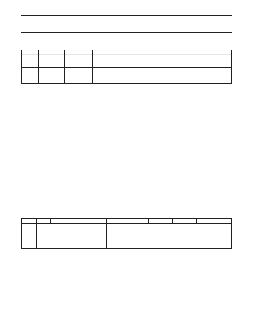
MR1 Mode Register 1
Bit 7
Rx
CONTROLS
RTS
BIT 6
RxINT
BIT 1
BIT 5
ERROR
MODE
Bit (4:3)
PARITY MODE
BIT 2
PARITY
TYPE
Bits (1:0)
BITS PER
CHARACTER
MR1 A
MR1 B
0 = No
1 = Yes
0 = RxRDY
1 = FFULL
0 = Char
1 = Block
00 = With Parity
01 = Force Parity
10 = No Parity
11 = Multi–drop Mode
0 = Even
1 = Odd
00 = 5
01 = 6
10 = 7
11 = 8
NOTE: * In block error mode the block error conditions must be cleared by using the error reset command (command 0x40) or a receiver reset.
MR1 A is accessed when the Channel A MR pointer points to MR1.
The pointer is set to MR1 by RESET or by a ‘set pointer’ command
applied via CR command 1. After reading or writing MR1 A, the
pointer will point to MR2 A.
MR1 A[7] – Channel A Receiver Request–to–Send Control (Flow
Control)
This bit controls the deactivation of the RTSN A output (I/O0 B) by
the receiver. This output is normally asserted by setting OPR[0]B
and negated by resetting OPR[0]B.
MR1 A[7] = 1 causes RTSN A to be negated (I/O0 B is driven to a ‘1’
[V
CC
]) upon receipt of a valid start bit if the Channel A FIFO is full.
This is the beginning of the reception of the ninth byte. If the FIFO is
not read before the start of the tenth byte, an overrun condition will
occur and the tenth byte will be lost. However, the bit in OPR[0] is
not reset and RTSN A will be asserted again when an empty FIFO
position is available. This feature can be used for flow control to
prevent overrun in the receiver by using the RTSN A output signal to
control the CTSN input of the transmitting device.
MR1[6] – Receiver interrupt control bit 1. See description under
MR0[6].
MR1 A[5] – Channel A Error Mode Select
This bit select the operating mode of the three FIFOed status bits
(FE, PE, received break) for Channel A. In the ‘character’ mode,
status is provided on a character–by–character basis; the status
applies only to the character at the top of the FIFO. In the ‘block’
mode, the status provided in the SR for these bits is the
accumulation (logical–OR) of the status for all characters coming to
the top of the FIFO since the last ‘reset error’ command for Channel
A was issued.
MR1 A[4:3| – Channel A Parity Mode Select
If ‘with parity’ or ‘force parity’ is selected a parity bit is added to the
transmitted character and the receiver performs a parity check on
incoming data
MR1 A[4:3] = 11 selects Channel A to operate in the special
multi–drop mode described in the Operation section.
MR1 A[2] – Channel A Parity Type Select
Selects the parity type (odd or even) if the “‘with parity” mode is
programmed by MR1 A[4:3], and the polarity of the forced parity bit if
the ‘force parity’ mode is programmed; no effect if ‘no parity’ is
programmed. In the special multi–drop mode it selects the polarity of
the A/D bit.
MR1 A[1:0] – Channel A Bits Per Character Select
This field selects the number of data bits per character to be
transmitted and received. The character length does not include the
start, parity, and stop bits.
MR2 A is accessed when the Channel A MR pointer points to MR2,
which occurs after any access to MR1 A. Accesses to MR2 A do not
change the pointer.
MR2 Mode Register 2
Bit 7
MR2 A
MR2 B
00 = Normal
01 = Auto–Echo
10 = Local loop
11 = Remote loop
NOTE: *Add 0.5 to values shown for 0 – 7 if channel is programmed
for 5 bits/char.
BIT 6
BIT 5
Tx CONTROLS RTS
BIT 4
CTS
ENABLE Tx
0 = No
1 = Yes
BIT 3
STOP BIT LENGTH
NOTE: Add 0.5 to binary codes 0 – 7 for 5 bit character lengths.
0 = 0.563 4 = 0.813 8 = 1.563 C = 1.813
1 = 0.625 5 = 0.875 9 = 1.625 D = 1.875
2 = 0.688 6 = 0.938 A = 1.688 E = 1.938
3 = 0.750 7 = 1.000 B = 1.750 F = 2.000
See description in the previous MR2 description
BIT 2
BIT 1
BIT 0
CHANNEL MODE
0 = No
1 = Yes
相關(guān)PDF資料 |
PDF描述 |
|---|---|
| SC28L202A1B | Dual universal asynchronous receiver/transmitter DUART |
| SC28L202A1D | Dual universal asynchronous receiver/transmitter DUART |
| SC431CS8DE2 | Analog IC |
| SC431CS8DE3 | Analog IC |
| SC431CS8DF1 | Analog IC |
相關(guān)代理商/技術(shù)參數(shù) |
參數(shù)描述 |
|---|---|
| SC28L202A1 | 制造商:PHILIPS 制造商全稱:NXP Semiconductors 功能描述:Dual universal asynchronous receiver/transmitter DUART |
| SC28L202A1B | 制造商:PHILIPS 制造商全稱:NXP Semiconductors 功能描述:Dual universal asynchronous receiver/transmitter DUART |
| SC28L202A1D | 制造商:PHILIPS 制造商全稱:NXP Semiconductors 功能描述:Dual universal asynchronous receiver/transmitter DUART |
| SC28L202A1DGG | 功能描述:UART 接口集成電路 3-5V 2CH UART 3MBPS 256B FIFO RoHS:否 制造商:Texas Instruments 通道數(shù)量:2 數(shù)據(jù)速率:3 Mbps 電源電壓-最大:3.6 V 電源電壓-最小:2.7 V 電源電流:20 mA 最大工作溫度:+ 85 C 最小工作溫度:- 40 C 封裝 / 箱體:LQFP-48 封裝:Reel |
| SC28L202A1DGG,112 | 功能描述:UART 接口集成電路 3-5V 2CH UART 3MBPS RoHS:否 制造商:Texas Instruments 通道數(shù)量:2 數(shù)據(jù)速率:3 Mbps 電源電壓-最大:3.6 V 電源電壓-最小:2.7 V 電源電流:20 mA 最大工作溫度:+ 85 C 最小工作溫度:- 40 C 封裝 / 箱體:LQFP-48 封裝:Reel |
發(fā)布緊急采購,3分鐘左右您將得到回復(fù)。