- 您現(xiàn)在的位置:買賣IC網(wǎng) > PDF目錄383682 > OMAP5910(DSP) Dual-Core Processor PDF資料下載
參數(shù)資料
| 型號(hào): | OMAP5910(DSP) |
| 英文描述: | Dual-Core Processor |
| 中文描述: | 雙核處理器 |
| 文件頁(yè)數(shù): | 40/160頁(yè) |
| 文件大小: | 1997K |
| 代理商: | OMAP5910(DSP) |
第1頁(yè)第2頁(yè)第3頁(yè)第4頁(yè)第5頁(yè)第6頁(yè)第7頁(yè)第8頁(yè)第9頁(yè)第10頁(yè)第11頁(yè)第12頁(yè)第13頁(yè)第14頁(yè)第15頁(yè)第16頁(yè)第17頁(yè)第18頁(yè)第19頁(yè)第20頁(yè)第21頁(yè)第22頁(yè)第23頁(yè)第24頁(yè)第25頁(yè)第26頁(yè)第27頁(yè)第28頁(yè)第29頁(yè)第30頁(yè)第31頁(yè)第32頁(yè)第33頁(yè)第34頁(yè)第35頁(yè)第36頁(yè)第37頁(yè)第38頁(yè)第39頁(yè)當(dāng)前第40頁(yè)第41頁(yè)第42頁(yè)第43頁(yè)第44頁(yè)第45頁(yè)第46頁(yè)第47頁(yè)第48頁(yè)第49頁(yè)第50頁(yè)第51頁(yè)第52頁(yè)第53頁(yè)第54頁(yè)第55頁(yè)第56頁(yè)第57頁(yè)第58頁(yè)第59頁(yè)第60頁(yè)第61頁(yè)第62頁(yè)第63頁(yè)第64頁(yè)第65頁(yè)第66頁(yè)第67頁(yè)第68頁(yè)第69頁(yè)第70頁(yè)第71頁(yè)第72頁(yè)第73頁(yè)第74頁(yè)第75頁(yè)第76頁(yè)第77頁(yè)第78頁(yè)第79頁(yè)第80頁(yè)第81頁(yè)第82頁(yè)第83頁(yè)第84頁(yè)第85頁(yè)第86頁(yè)第87頁(yè)第88頁(yè)第89頁(yè)第90頁(yè)第91頁(yè)第92頁(yè)第93頁(yè)第94頁(yè)第95頁(yè)第96頁(yè)第97頁(yè)第98頁(yè)第99頁(yè)第100頁(yè)第101頁(yè)第102頁(yè)第103頁(yè)第104頁(yè)第105頁(yè)第106頁(yè)第107頁(yè)第108頁(yè)第109頁(yè)第110頁(yè)第111頁(yè)第112頁(yè)第113頁(yè)第114頁(yè)第115頁(yè)第116頁(yè)第117頁(yè)第118頁(yè)第119頁(yè)第120頁(yè)第121頁(yè)第122頁(yè)第123頁(yè)第124頁(yè)第125頁(yè)第126頁(yè)第127頁(yè)第128頁(yè)第129頁(yè)第130頁(yè)第131頁(yè)第132頁(yè)第133頁(yè)第134頁(yè)第135頁(yè)第136頁(yè)第137頁(yè)第138頁(yè)第139頁(yè)第140頁(yè)第141頁(yè)第142頁(yè)第143頁(yè)第144頁(yè)第145頁(yè)第146頁(yè)第147頁(yè)第148頁(yè)第149頁(yè)第150頁(yè)第151頁(yè)第152頁(yè)第153頁(yè)第154頁(yè)第155頁(yè)第156頁(yè)第157頁(yè)第158頁(yè)第159頁(yè)第160頁(yè)
Introduction
28
August 2002 Revised August 2003
SPRS197B
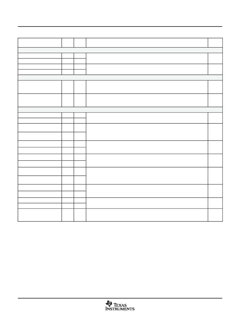
Table 24. Signal Description (Continued)
GDY
BALL
SIGNAL
TYPE
DESCRIPTION
GZG
BALL
Multichannel Serial Interfaces (MCSIs) (Continued)
MCSI1.DIN
W13
R10
MCSI data in. Multichannel Serial Interface data input pin.
I
MCSI2.DIN
AA9
P8
MCSI1.DOUT
W14
N12
MCSI data out. Multichannel Serial Interface data output pin.
O
MCSI2.DOUT
W9
T7
USB (Integrated Transceiver Interface, can be used with Host or Function)
USB.DP
P9
P5
USB internal transceiver D+. The positive side of the integrated USB transceiver’s
differential bus. A series resistor of 27
(5% tolerance) is required on the
USB.DP pin.
I/O/Z
USB.DM
R8
P4
USB internal transceiver D. The negative side of the integrated USB
transceiver’s differential bus. A series resistor of 27
(5% tolerance) is required
on the USB.DM pin.
I/O/Z
USB Pin Group 1 and 2 (Utilizing External Transceivers, can be used with Host or Function)
USB2.TXEN
W9
T7
USB transmit data. Single-ended logic output used to transmit data to the transmit
USB2.TXD
V6
R4
device.
USB1.TXEN
W16
T6
O
USB transmit enable. Driven active (high) when the USB host or Function
peripheral is driving data onto the USB bus via the TXD output.
USB1.TXD
W14
N12
O
input of an external USB transceiver. USBx.TXD may also be used for
transceiverless connection between OMAP5910 and another transceiverless USB
USB1.VP
V13
T11
USB vplus data. Single-ended input used to monitor the logical state of the D+ line
of the USB bus. USBx.VP should be driven by an external USB transceiver based
on the state of D+.
I
USB2.VP
AA9
P8
USB1.VM
AA13
U11
USB vminus data. Single-ended input used to monitor the logical state of the D
line of the USB bus. USBx.VM should be driven by an external USB transceiver
based on the state of D.
I
USB2.VM
R9
M7
USB1.RCV
W13
R10
USB receive data. Single-ended logic input used to receive data from the receive
output of an external USB transceiver. USBx.RCV may also be used for
transceiverless connection between OMAP5910 and another transceiverless USB
device.
I
USB2.RCV
Y5
N6
USB1.SUSP
AA17
R12
USB bus segment suspend control. Active-high output indicates detection of IDLE
condition on the USB bus for greater than 5 ms. USBx.SUSP is implemented on
both USB ports 1 and 2.
O
USB2.SUSP
Y10
T8
USB1.SE0
P14
U13
zero state on the USB bus. USBx.SE0 is implemented for both USB ports 1 and 2.
O
USB2.SE0
W5
U4
USB single-ended zero. Active-high output indicates detection of the single-ended
USB1.SPEED
Y12
N10
USB 1 bus segment speed control. Static control output used by the external
transceiver to determine whether USB port 1 is operating in full-speed or
low-speed mode. USB1.SPEED is only implemented on USB port 1.
O
I = Input, O = Output, Z = High-Impedance
All core voltage supplies should be tied to the same voltage level (within 0.3 V). During system prototyping phases, it may be useful to maintain
a capability for independent measurement of core supply currents to facilitate power optimization experiments.
§See Sections 5.6.1 and 5.6.2 for special VSS considerations with oscillator circuits.
相關(guān)PDF資料 |
PDF描述 |
|---|---|
| OMAP5910(RISC) | Dual-Core Processor |
| OMC506 | Closed Loop Speed Controller For 3-Phase Brushless DC Motor MP-3T Package |
| OMC507 | 5 Amp. Push-Pull 3-Phase Brushless DC Motor Controller Driver(5A,推挽三相無(wú)刷直流電機(jī)控制驅(qū)動(dòng)器) |
| OMC510 | 36V Hi-Rel Three-Phase Brushless DC Motor Controller in a PCB-1 package |
| OMC510 | DSP-Based Three-Phase Brushless DC Motor Controller(基于DSP的三相無(wú)刷直流電機(jī)控制器) |
相關(guān)代理商/技術(shù)參數(shù) |
參數(shù)描述 |
|---|---|
| OMAP5910GGZG1 | 制造商:Rochester Electronics LLC 功能描述:- Bulk |
| OMAP5910GGZG2 | 制造商:Rochester Electronics LLC 功能描述:- Bulk |
| OMAP5910JGDY1R | 功能描述:IC OMAP DUAL-CORE PROC 289-BGA RoHS:是 類別:集成電路 (IC) >> 嵌入式 - 微處理器 系列:OMAP-59xx 標(biāo)準(zhǔn)包裝:60 系列:SCC 處理器類型:Z380 特點(diǎn):全靜電 Z380 CPU 速度:20MHz 電壓:5V 安裝類型:表面貼裝 封裝/外殼:144-LQFP 供應(yīng)商設(shè)備封裝:144-LQFP 包裝:托盤 |
| OMAP5910JGDY2 | 功能描述:數(shù)字信號(hào)處理器和控制器 - DSP, DSC Applications Proc RoHS:否 制造商:Microchip Technology 核心:dsPIC 數(shù)據(jù)總線寬度:16 bit 程序存儲(chǔ)器大小:16 KB 數(shù)據(jù) RAM 大小:2 KB 最大時(shí)鐘頻率:40 MHz 可編程輸入/輸出端數(shù)量:35 定時(shí)器數(shù)量:3 設(shè)備每秒兆指令數(shù):50 MIPs 工作電源電壓:3.3 V 最大工作溫度:+ 85 C 封裝 / 箱體:TQFP-44 安裝風(fēng)格:SMD/SMT |
| OMAP5910JGZG1 | 制造商:Texas Instruments 功能描述: |
發(fā)布緊急采購(gòu),3分鐘左右您將得到回復(fù)。