- 您現(xiàn)在的位置:買賣IC網(wǎng) > PDF目錄383236 > L6238 (意法半導體) Sensorless Spindle Motor Driver(無傳感器主軸電機驅動器) PDF資料下載
參數(shù)資料
| 型號: | L6238 |
| 廠商: | 意法半導體 |
| 英文描述: | Sensorless Spindle Motor Driver(無傳感器主軸電機驅動器) |
| 中文描述: | 傳感器主軸電機驅動器(無傳感器主軸電機驅動器) |
| 文件頁數(shù): | 3/35頁 |
| 文件大小: | 383K |
| 代理商: | L6238 |
第1頁第2頁當前第3頁第4頁第5頁第6頁第7頁第8頁第9頁第10頁第11頁第12頁第13頁第14頁第15頁第16頁第17頁第18頁第19頁第20頁第21頁第22頁第23頁第24頁第25頁第26頁第27頁第28頁第29頁第30頁第31頁第32頁第33頁第34頁第35頁
GENERAL DESCRIPTION
The L6238 is an integrated circuit that will be
used to commutate and speed control a 3-Phase,
8-pole, brushless, DC motor. The primary applica-
tion is for disk drive spindle motors. This I.C. has
the following features:
No Motor Hall Effect Sensors are required for
commutation or speedcontrol. Timing informa-
tion is determined from the Bemf voltage of the
undriven motor terminal.
On-board Speed Control via a Phase Locked
Loop that accepts a once-per-rev reference
frequency and locks the motor to that fre-
quency. The L6238 can accomodate a wide
range of speeds.
The L6238 achieves Spindle Synchronization
by locking to a once-per-rev reference that is
common to multiple drives. The L6238 has a
multiplexer that enhances the versatility of the
controller. This first multiplexer selects either
internal feedback, (generated by the Bemf of
the motor), or external feedback (embedded
index).
An External P-Channel FET can be connected
to the FET can be connected to the FET
Bridge for HigherPower Applications.
In this configuration, the internal DMOS drivers
are sequenced in full conductionstate and the
external PFET is the linear control element. An
internal inverting buffer from the output of the
OTAcontrols the conductionof the EXT PFET.
An internal Virtual Center Tap is used if the
motorcenter tap is not connected.
The motor Current Limit can be set by an ex-
ternalresistor divider.
A Serial Port is included so that I/O can be
done with a minimum of pins. Key control and
status lines are also bonded out to achieve a
Minimum Configurationwithout using the Serial
Port.
Programmable
Functions
Switch Timing Optimization for motor effi-
ciency, Speed Lock Threshold, Auto-Start or
mP Supervised Spinup, and output current lim-
itinggain.
Energy Recovery Mode for Head Retraction,
followedby Dynamic Braking Mode.
Logic signals are CMOS Compatible.
Stuck Rotor and Backward Rotationdetection.
Automatic Thermal Shutdown with early warn-
ing bit available in the statusregister
include
Phase
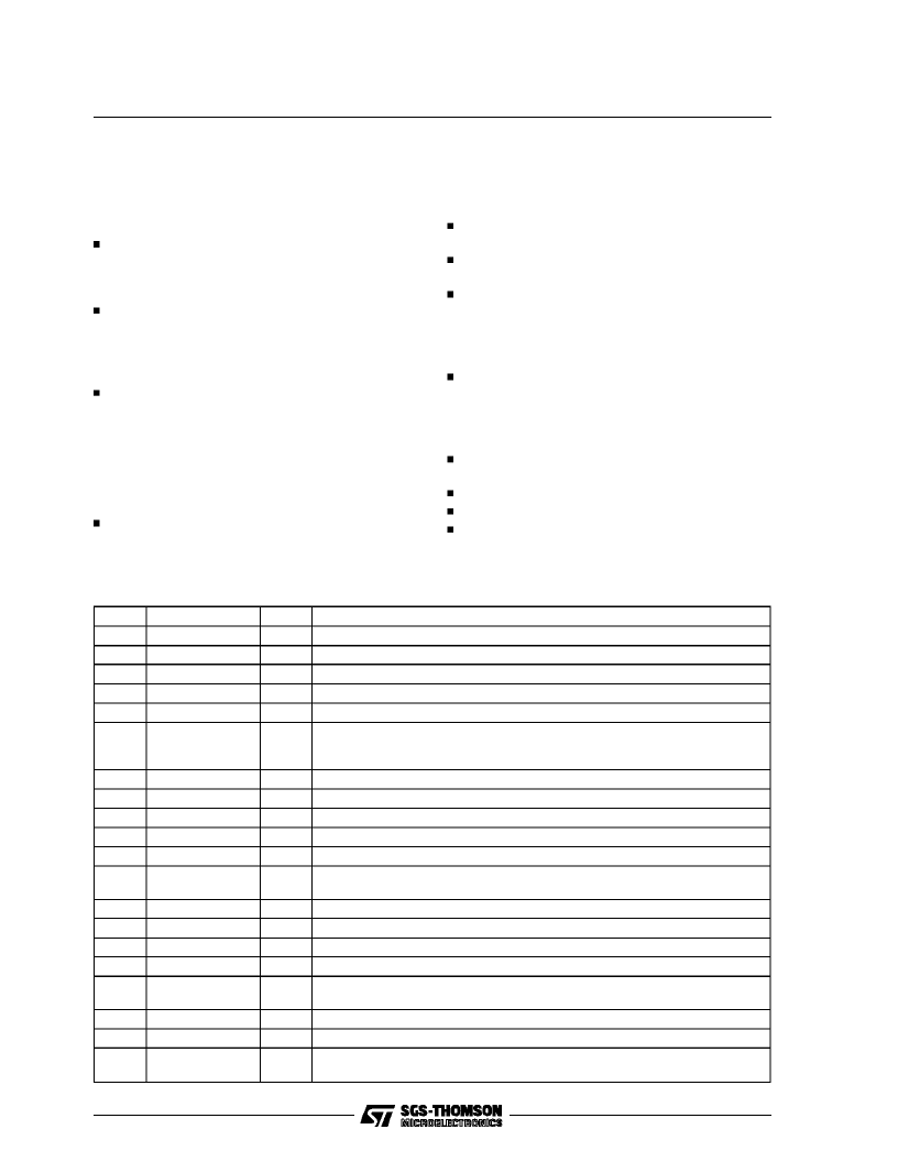
PIN FUNCTIONS
N.
1
2
3
4
5
Name
OUTPUT B
SPIN SENSE
BRAKE DELAY
R
sense
CHARGE PUMP 2
GROUND
I/O
I/O
O
I
O
I
I
Function
DMOS HalfBridge Output and Input B for Bemf sensing.
Toggless at each Zero Crossing of the Bemf.
Energy Recovery time constant, definedby external R-C to ground.
Outputs A+B connections for the Motor Current Sense Resistor to ground
Negative Terminal of Pump Capacitor.
Ground terminals.
6, 7,
17, 29,
39, 40
8
9
10
11, 42
12
13
CHARGE PUMP 1
CHARGE PUMP 3
OUTPUT A
V
power
V
analog
SER PORT
DISABLE
SER DATA R/W
SER STROBE
SER PORT CLK
SER DATA I/O
EXT/INT
I
I
Positive terminal of Pump Capacitor.
Positive terminal of StorageCapacitor.
DMOS HalfBridge Output and Input A for Bemf sensing.
Supplies the voltage for the Power Section.
12V supply.
Input for tri-stating the serial port.
I/O
I
I
I
14
15
16
18
19
I
I
I
Selects Serial Data Read or Write Function.
Dtat Strobe Input.
Clock for Serial Data Control.
Data stream Input/Output for Control/Status Registers.
Selects thr Internal BEMF Zero Crossing or an External Source as Feedback
Frequency for te PLL.
A zero on this pin passes the PLL Fref signal to the Freq/phase detector.
This input should be grounded or leftunconnected.
Tristates PowerOutput Stage when a logic zero.
I/O
I
20
21
22
FREF ENABLE
LINEAR
OUTPUT
ENABLE
I
I
I
L6238
3/35
相關PDF資料 |
PDF描述 |
|---|---|
| L6239 | 12V Disk Drive Spindle Driver(12V磁盤驅動主軸驅動器) |
| L6242 | VOICE COIL MOTOR DRIVER |
| L6243 | VOICE COIL MOTOR DRIVER |
| L6243D | VOICE COIL MOTOR DRIVER |
| L6243DS | VOICE COIL MOTOR DRIVER |
相關代理商/技術參數(shù) |
參數(shù)描述 |
|---|---|
| L6238S | 制造商:STMICROELECTRONICS 制造商全稱:STMicroelectronics 功能描述:12V SENSORLESS SPINDLE MOTOR CONTROLLER |
| L6238SQA | 制造商:STMICROELECTRONICS 制造商全稱:STMicroelectronics 功能描述:12V SENSORLESS SPINDLE MOTOR CONTROLLER |
| L6238SQT | 制造商:STMICROELECTRONICS 制造商全稱:STMicroelectronics 功能描述:12V SENSORLESS SPINDLE MOTOR CONTROLLER |
| L6239 | 制造商:未知廠家 制造商全稱:未知廠家 功能描述: |
| L623C | 制造商:未知廠家 制造商全稱:未知廠家 功能描述:THYRISTOR MODULE|BRIDGE|HALF-CNTLD|CA|280V V(RRM)|46A I(T) |
發(fā)布緊急采購,3分鐘左右您將得到回復。