- 您現(xiàn)在的位置:買(mǎi)賣(mài)IC網(wǎng) > PDF目錄377496 > INTELDX2 (Intel Corp.) High-Performance 32-Bit Embedded Processor(高性能32位嵌入式處理器) PDF資料下載
參數(shù)資料
| 型號(hào): | INTELDX2 |
| 廠商: | Intel Corp. |
| 英文描述: | High-Performance 32-Bit Embedded Processor(高性能32位嵌入式處理器) |
| 中文描述: | 高性能32位嵌入式處理器(高性能32位嵌入式處理器) |
| 文件頁(yè)數(shù): | 24/48頁(yè) |
| 文件大小: | 486K |
| 代理商: | INTELDX2 |
第1頁(yè)第2頁(yè)第3頁(yè)第4頁(yè)第5頁(yè)第6頁(yè)第7頁(yè)第8頁(yè)第9頁(yè)第10頁(yè)第11頁(yè)第12頁(yè)第13頁(yè)第14頁(yè)第15頁(yè)第16頁(yè)第17頁(yè)第18頁(yè)第19頁(yè)第20頁(yè)第21頁(yè)第22頁(yè)第23頁(yè)當(dāng)前第24頁(yè)第25頁(yè)第26頁(yè)第27頁(yè)第28頁(yè)第29頁(yè)第30頁(yè)第31頁(yè)第32頁(yè)第33頁(yè)第34頁(yè)第35頁(yè)第36頁(yè)第37頁(yè)第38頁(yè)第39頁(yè)第40頁(yè)第41頁(yè)第42頁(yè)第43頁(yè)第44頁(yè)第45頁(yè)第46頁(yè)第47頁(yè)第48頁(yè)
Embedded IntelDX2 Processor
20
BOFF#
I
Backoff
nput forces the embedded IntelDX2 processor to float its bus in the next
clock. The processor floats all pins normally floated during bus hold but HLDA is
not asserted in response to BOFF#. BOFF# has higher priority than RDY# or
BRDY#; if both are returned in the same clock, BOFF# takes effect. The
embedded IntelDX2 processor remains in bus hold until BOFF# is negated. If a
bus cycle is in progress when BOFF# is asserted the cycle is restarted. BOFF# is
active LOW and must meet setup and hold times t
18
and t
19
for proper operation.
CACHE INVALIDATION
AHOLD
I
Address Hold
request allows another bus master access to the embedded
IntelDX2 processor’s address bus for a cache invalidation cycle. The processor
stops driving its address bus in the clock following AHOLD going active. Only the
address bus is floated during address hold, the remainder of the bus remains
active. AHOLD is active HIGH and is provided with a small internal pull-down
resistor. For proper operation, AHOLD must meet setup and hold times t
18
and
t
19
.
External Address
- This signal indicates that a
valid
external address has been
driven onto the embedded IntelDX2 processor address pins. This address is used
to perform an internal cache invalidation cycle. EADS# is active LOW and is
provided with an internal pull-up resistor. EADS# must satisfy setup and hold
times t
12
and t
13
for proper operation.
EADS#
I
CACHE CONTROL
KEN#
I
Cache Enable
pin is used to determine whether the current cycle is cacheable.
When the embedded IntelDX2 processor generates a cycle that can be cached
and KEN# is active one clock before RDY# or BRDY# during the first transfer of
the cycle, the cycle becomes a cache line fill cycle. Returning KEN# active one
clock before RDY# during the last read in the cache line fill causes the line to be
placed in the on-chip cache. KEN# is active LOW and is provided with a small
internal pull-up resistor. KEN# must satisfy setup and hold times t
14
and t
15
for
proper operation.
Cache Flush
input forces the embedded IntelDX2 processor to flush its entire
internal cache. FLUSH# is active LOW and need only be asserted for one clock.
FLUSH# is asynchronous but setup and hold times t
20
and t
21
must be met for
recognition in any specific clock.
FLUSH#
I
PAGE CACHEABILITY
PWT
PCD
O
O
Page Write-Through
and
Page Cache Disable
pins reflect the state of the page
attribute bits, PWT and PCD, in the page table entry, page directory entry or
control register 3 (CR3) when paging is enabled. When paging is disabled, the
embedded IntelDX2 processor ignores the PCD and PWT bits and assumes they
are zero for the purpose of caching and driving PCD and PWT pins. PWT and
PCD have the same timing as the cycle definition pins (M/IO#, D/C#, and W/R#).
PWT and PCD are active HIGH and are not driven during bus hold. PCD is
masked by the cache disable bit (CD) in Control Register 0.
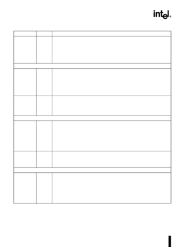
Table 8.
Embedded IntelDX2 Processor Pin Descriptions
(Sheet 5 of 7)
Symbol
Type
Name and Function
相關(guān)PDF資料 |
PDF描述 |
|---|---|
| INTELDX4 | Embedded Write-Back Enhanced Processor(32位回復(fù)嵌入式增強(qiáng)型處理器) |
| IPS54511 | FULLY PROTECTED HIGH SIDE POWER MOSFET SWITCH |
| IPS5451 | FULLY PROTECTED HIGH SIDE POWER MOSFET SWITCH |
| IPS5451S | FULLY PROTECTED HIGH SIDE POWER MOSFET SWITCH |
| IPS5751 | FULLY PROTECTED HIGH SIDE POWER MOSFET SWITCH |
相關(guān)代理商/技術(shù)參數(shù) |
參數(shù)描述 |
|---|---|
| INTELLIGENT CHARGER + 4AA | 制造商:Energizer 功能描述:Bulk |
| INTELLI-INCH-LR-STARTER K | 制造商:ALL MOTION 功能描述:Intelli-Inch Stepper & Controller Starter Kit |
| INTELLIPANEL | 制造商:GJD 功能描述:EXTENSION LEAD 8GANG INTELLIPANEL 制造商:GJD 功能描述:EXTENSION LEAD, 8GANG, INTELLIPANEL |
| INTELLIPLUG | 制造商:GLOBAL COMMUNICATIONS 功能描述:ADAPTOR 3WAY INTELLIPLUG |
| INTELLIPROBE 100 | 制造商:Fluke Networks 功能描述:TONE + PROBE KIT |
發(fā)布緊急采購(gòu),3分鐘左右您將得到回復(fù)。