- 您現(xiàn)在的位置:買賣IC網(wǎng) > PDF目錄379203 > IBM025160 (IBM Microeletronics) 4Mb(256K X 16) MULTIPORT VIDEO RAM(4M位(256K X 16)多端口視頻RAM) PDF資料下載
參數(shù)資料
| 型號(hào): | IBM025160 |
| 廠商: | IBM Microeletronics |
| 英文描述: | 4Mb(256K X 16) MULTIPORT VIDEO RAM(4M位(256K X 16)多端口視頻RAM) |
| 中文描述: | 4Mb的(256 × 16)多端口視頻內(nèi)存(4分位(256 × 16)多端口視頻內(nèi)存) |
| 文件頁(yè)數(shù): | 51/65頁(yè) |
| 文件大小: | 841K |
| 代理商: | IBM025160 |
第1頁(yè)第2頁(yè)第3頁(yè)第4頁(yè)第5頁(yè)第6頁(yè)第7頁(yè)第8頁(yè)第9頁(yè)第10頁(yè)第11頁(yè)第12頁(yè)第13頁(yè)第14頁(yè)第15頁(yè)第16頁(yè)第17頁(yè)第18頁(yè)第19頁(yè)第20頁(yè)第21頁(yè)第22頁(yè)第23頁(yè)第24頁(yè)第25頁(yè)第26頁(yè)第27頁(yè)第28頁(yè)第29頁(yè)第30頁(yè)第31頁(yè)第32頁(yè)第33頁(yè)第34頁(yè)第35頁(yè)第36頁(yè)第37頁(yè)第38頁(yè)第39頁(yè)第40頁(yè)第41頁(yè)第42頁(yè)第43頁(yè)第44頁(yè)第45頁(yè)第46頁(yè)第47頁(yè)第48頁(yè)第49頁(yè)第50頁(yè)當(dāng)前第51頁(yè)第52頁(yè)第53頁(yè)第54頁(yè)第55頁(yè)第56頁(yè)第57頁(yè)第58頁(yè)第59頁(yè)第60頁(yè)第61頁(yè)第62頁(yè)第63頁(yè)第64頁(yè)第65頁(yè)
IBM025160
IBM025161
IBM025170
IBM025171
256K X 16 MULTIPORT VIDEO RAM
33G0307
SA14-4751-05
Revised 3/98
IBM Corporation, 1995. All rights reserved.
Use is further subject to the provisions at the end of this document.
Page 51 of 65
Transfer Modes
The following Transfer Modes are available:
1. Full Read Transfer (Normal) Mode.
2. Split Read Transfer (Normal) Mode.
3. Full Read Transfer (SRS) Mode.
4. Split Read Transfer (SRS) Mode.
5. Full Write Transfer (Normal) Mode.
6. Split Write Transfer (Normal) Mode.
7. Full Write Transfer (SRS) Mode.
8. Split Write Transfer (SRS) Mode.
Full Register Read Transfer (Normal) Mode
The Full Register Read Transfer operation is illustrated in the timing diagram on page 41. This operation will
load the entire SAM (256 x16 bits) from the selected segment of the row. CA
8
controls which half of the
selected row needs to be transferred. If CA
8
at CE fall time is “0”, the lower half of the selected row is trans-
ferred. If CA
8
at CE fall time is “1”, the upper half of the selected row is transferred. CA
7
-CA
0
address sup-
plied by the user at CE fall time is used to provide the starting address for reading of data from the Serial port.
The SAM has 256 locations to be addressed starting from 0 to 255. During the Full Read Transfer cycle the
Start Address Register as well as the Serial port counter will be loaded, with the user supplied address CA
7
-
CA
0
. CA
7
equals “0” is associated with the lower half of the SAM and CA
7
equals “1” is associated with the
upper half of the SAM. A Full Register Read Transfer from the selected row to SAM is shown in the timing
diagram on page 51. The example shows a transfer based on user supplied CA
8
equals “1”. The Serial port
counter is set to the address CA
7
-CA
0
specified by the user at CE fall time during the Full Read Transfer
cycle. The next SC cycle following the transfer will start reading data from this point in the SAM. Reading will
continue until the end of the SAM location 256 and will wrap around. To keep Serial data out continuous,
either a Split Read Transfer or a Full Read Transfer must be executed as the SAM runs out of new data. See
the timing diagrams for the necessary timing requirements for either method of loading the SAM
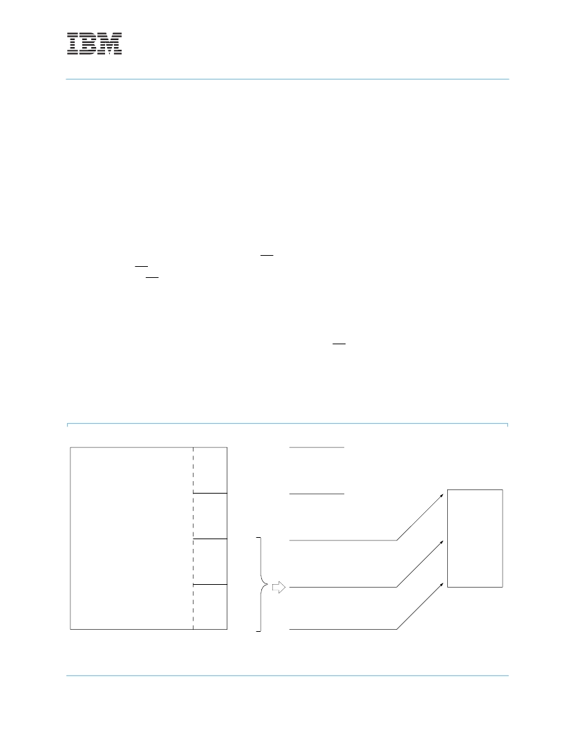
Full Register Read Transfer (Normal) Mode
Array
511
0
383
511
Rows
Cols
SAM
0
127
128
255
255
127
CA
7
=0 CA
8
=0
CA
7
=1 CA
8
=0
CA
7
=0 CA
8
=1
CA
7
=1 CA
8
=1
相關(guān)PDF資料 |
PDF描述 |
|---|---|
| IBM025161 | 4Mb(256K X 16) MULTIPORT VIDEO RAM(4M位(256K X 16)多端口視頻RAM) |
| IBM025170 | 4Mb(256K X 16) MULTIPORT VIDEO RAM(4M位(256K X 16)多端口視頻RAM) |
| IBM025171 | 4Mb(256K X 16) MULTIPORT VIDEO RAM(4M位(256K X 16)多端口視頻RAM) |
| IBM038329NL6B | 256K x 32 Synchronous Graphics RAM(256K x 32 高性能8M位CMOS同步動(dòng)態(tài)RAM(帶內(nèi)置的圖形性能)) |
| IBM038329NP6B | 256K x 32 Synchronous Graphics RAM(256K x 32 高性能8M位CMOS同步動(dòng)態(tài)RAM(帶內(nèi)置的圖形性能)) |
相關(guān)代理商/技術(shù)參數(shù) |
參數(shù)描述 |
|---|---|
| IBM025160LG5B-70 | 制造商:IBM 功能描述: |
| IBM02N6153 | 制造商:AVED Memory Products 功能描述: |
| IBM02N7991 | 制造商:AVED Memory Products 功能描述: |
| IBM02N7994 | 制造商:AVED Memory Products 功能描述: |
| IBM0312164PT3A360 | 制造商:IBM 功能描述:* |
發(fā)布緊急采購(gòu),3分鐘左右您將得到回復(fù)。