- 您現(xiàn)在的位置:買賣IC網 > PDF目錄383075 > HSP50214AVC (HARRIS SEMICONDUCTOR) Programmable Downconverter PDF資料下載
參數資料
| 型號: | HSP50214AVC |
| 廠商: | HARRIS SEMICONDUCTOR |
| 元件分類: | 通信及網絡 |
| 英文描述: | Programmable Downconverter |
| 中文描述: | SPECIALTY TELECOM CIRCUIT, PQFP120 |
| 文件頁數: | 33/60頁 |
| 文件大小: | 467K |
| 代理商: | HSP50214AVC |
第1頁第2頁第3頁第4頁第5頁第6頁第7頁第8頁第9頁第10頁第11頁第12頁第13頁第14頁第15頁第16頁第17頁第18頁第19頁第20頁第21頁第22頁第23頁第24頁第25頁第26頁第27頁第28頁第29頁第30頁第31頁第32頁當前第33頁第34頁第35頁第36頁第37頁第38頁第39頁第40頁第41頁第42頁第43頁第44頁第45頁第46頁第47頁第48頁第49頁第50頁第51頁第52頁第53頁第54頁第55頁第56頁第57頁第58頁第59頁第60頁
33
Serial Direct Output Port Mode
The Serial Direct Output Port Mode offers the ability to con-
struct two serial output data streams, SEROUTA AND
SEROUTB, from 16-bit I, Q, magnitude, phase, frequency, tim-
ing error, and AGC level data words. The total number of data
words (1 to 8) for serial output, and the sequential order of
these data word components of the serial output are program-
mable. Each data word may be used once in either the
SEROUTA or SEROUTB data streams. Figure 31 illustrates the
conceptual implementation of the Serial Direct Output Port
Mode.
In the Serial Direct Mode, the output data is loaded into
Serial Shift Registers and routed to two serial output pins,
SEROUTA and SEROUTB. The serial output shift clock,
SERCLK, is PROCCLK divided by 1, 2, 4, 8, or 16. The
divide down ratio is programmed using Control Word 20,
Bits 14-16. The data is shifted out on the rising edge of the
internal SERCLK. The external clock polarity of SERCLK is
programmable via Control Word 20, Bit 18. A sync signal is
provided for detection of the start or end of each word in
the serial sequence. Control Word 20, Bit 17, sets the
SERSYNC signal location as either preceding the MSB
(typical for interfacing with microprocessors) or following
the LSB (typical for interfacing to D/A converters). Control
Word 20, Bit 19, sets the SERSYNC polarity as active low
or high. The LSB of each data word can be configured as
either the true LSB data, or set at a fixed logic “1” or “0” for
use as a tag bit. Control Word 20, Bits 0-13 set the LSB of
each of the 7 types of data words that can be configured in
the serial output stream. Control Word 19, Bits 21-24 set
the number of serial data words that will be linked to form
the serial outputs. Up to 7 data words can be linked to form
the serial output. SEROUTA and SEROUTB will have an
identical number of words in the serial output streams.
The 16-bit I, Q, magnitude, phase, frequency, timing error,
AGC level, and “zeros” data words are loaded into their
respective shift registers. The Magnitude and AGC Level
data word are unsigned binary format with a leading zero,
while the remaining signals are 2’s complement format.
Any of the eight data sources can be selected as the first
serial word for SEROUTA or SEROUTB. Control Word 19,
Bits 25-30 set the data type for the first serial word for
SEROUTA and SEROUTB. The three bit data type identifier
is shown both in Table 13 and in Figure 34, to the right of
the controls for the cross matrix switch. Serial output data
word sequences are formed by linking data words by pro-
gramming the data source for each shift requester’s shift
input signal. This programming links the Shift Registers
together in one or two serial chains. Thus, the Control Word
19 term “Link follows X data”, where X is one of the seven
data types. Once the data source data word is selected (by
programming a three bit word representing one of the data
types into Control Word 19, Bits 25-27 (SEROUTA), and
28-30 (SEROUTB)), the process for identifying the next
word is to select a three bit data type identifier which repre-
sents the data type to follow the source data type. Program
these bits into the Control Word 19 field representing the
“Link following X data”, where X = the source data type,
defines the second word in the sequence. Likewise, the
third data word is linked by selecting the Control Word 19
bits that identify the “Link following X data”, where X = the
data type of the second word in the serial chain. The pro-
cess continues until all the desired data words have been
linked.
NOTE: I and Q are sample aligned in time. |r| and
φ
are sample
aligned in time, but one sample delayed from I or Q. The
frequency sample is delayed in time from I or Q by 1 sam-
ple time + 63 tap FIR impulse response. If the FIR is set to
decimate, the FIR output will be repeated every sample
time until a new value appears at the filter output. (i.e., the
frequency samples are clocked out at the I, Q sample rate
regardless of decimation.)
Two examples will illustrate the process of configuring a serial
output using the Serial Output mode.
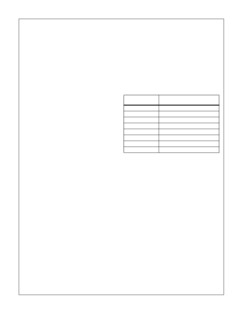
TABLE 13. LINKING CONTROL WORDS FOR SERIAL OUTPUT
DATA TYPE
IDENTIFIER
DATA TYPE
000
I Data
001
Q Data
010
Magnitude (MAG) Data
011
Phase (PHAS) Data
100
Frequency (FREQ) Data
101
Timing Error (TIMER) Data
110
AGC Gain
111
Zeros
HSP50214A
相關PDF資料 |
PDF描述 |
|---|---|
| HSP50214AVI | Programmable Downconverter |
| HSP50214B | Programmable Downconverter |
| HSP50214BVC | Programmable Downconverter |
| HSP50214BVI | Programmable Downconverter |
| HT84 | ADSL Coupling Transformers |
相關代理商/技術參數 |
參數描述 |
|---|---|
| HSP50214AVI | 制造商:INTERSIL 制造商全稱:Intersil Corporation 功能描述:Programmable Downconverter |
| HSP50214B | 制造商:INTERSIL 制造商全稱:Intersil Corporation 功能描述:Programmable Downconverter |
| HSP50214B_07 | 制造商:INTERSIL 制造商全稱:Intersil Corporation 功能描述:Programmable Downconverter |
| HSP50214BVC | 功能描述:上下轉換器 120L MQFP COMTEMP 14-BIT PROGRAMMABLE DOWNCONVERTER 65MSPS RoHS:否 制造商:Texas Instruments 產品:Down Converters 射頻:52 MHz to 78 MHz 中頻:300 MHz LO頻率: 功率增益: P1dB: 工作電源電壓:1.8 V, 3.3 V 工作電源電流:120 mA 最大功率耗散:1 W 最大工作溫度:+ 85 C 安裝風格:SMD/SMT 封裝 / 箱體:PQFP-128 |
| HSP50214BVCZ | 功能描述:上下轉換器 120L MQFP COMTEMP 14-BIT PROG DWNCNVRT RoHS:否 制造商:Texas Instruments 產品:Down Converters 射頻:52 MHz to 78 MHz 中頻:300 MHz LO頻率: 功率增益: P1dB: 工作電源電壓:1.8 V, 3.3 V 工作電源電流:120 mA 最大功率耗散:1 W 最大工作溫度:+ 85 C 安裝風格:SMD/SMT 封裝 / 箱體:PQFP-128 |
發(fā)布緊急采購,3分鐘左右您將得到回復。