- 您現(xiàn)在的位置:買賣IC網(wǎng) > PDF目錄383075 > HSP50214AVC (HARRIS SEMICONDUCTOR) Programmable Downconverter PDF資料下載
參數(shù)資料
| 型號: | HSP50214AVC |
| 廠商: | HARRIS SEMICONDUCTOR |
| 元件分類: | 通信及網(wǎng)絡(luò) |
| 英文描述: | Programmable Downconverter |
| 中文描述: | SPECIALTY TELECOM CIRCUIT, PQFP120 |
| 文件頁數(shù): | 27/60頁 |
| 文件大小: | 467K |
| 代理商: | HSP50214AVC |
第1頁第2頁第3頁第4頁第5頁第6頁第7頁第8頁第9頁第10頁第11頁第12頁第13頁第14頁第15頁第16頁第17頁第18頁第19頁第20頁第21頁第22頁第23頁第24頁第25頁第26頁當(dāng)前第27頁第28頁第29頁第30頁第31頁第32頁第33頁第34頁第35頁第36頁第37頁第38頁第39頁第40頁第41頁第42頁第43頁第44頁第45頁第46頁第47頁第48頁第49頁第50頁第51頁第52頁第53頁第54頁第55頁第56頁第57頁第58頁第59頁第60頁
27
In burst systems (such as TDMA), time resolution is needed
for quickly identifying the optimum sample point. The timing
is adjusted by shifting the decimation in the DSP
μ
P to the
closest sample. Use of timing error in this way may yield a
faster acquisition than a phase-locked loop coherent bit syn-
chronization. Finding the optimum sample point minimizes
intersymbol interference.
Fine time resolution is needed in CDMA systems to resolve
different multipath rays. In CDMA systems, the demands on
the programmable FIR can only be relieved by the re-sam-
pler/interpolation halfband filters. Assume the chip rate for a
baseband CDMA system is 1.2288MHz and PROCCLK is lim-
ited to 55MHz. Using the symmetric filter pre-sum approach,
PROCCLK limits the programmable FIR to 110MIPS (millions
of instructions per second) effective due to symmetry. If the
CDMA filter (loaded into the programmable FIR Section)
requires an impulse response with a span of 12 chips, the fil-
ter at 2x the chip-rate would need 24 taps. The 24 taps would
translate into 59MIPS = (1.2288MHz)(2)(24). To get the same
filtering at 8x the chip rate would require 944MIPS =
(1.2288MHz)(8)(96). Direct 8x filtering can not be accom-
plished with the programmable filter alone because 944MIPS
are much greater that the 60MIPs effective limit set by PROC-
CLK. It is necessary to decimate down to 2x the chip rate to
get a realistic number of filter taps. Both interpolation halfband
filters are then used to obtain the 8x CDMA output. 944 MIPS
is a lot of MIPS. The HSP50214A gets the equivalent process-
ing by decimating down and interpolating back up.
Timing NCO
The Timing NCO is very similar to the carrier NCO Phase
Accumulator Section. It provides the NCO driven sample
pulse and associated phase information to the resampling
filter process described in the Re-sampler Filter Section.
The Timing NCO does not include the SIN/COS Section
found in the Carrier NCO. The top level block diagram is
shown in Figure 26.
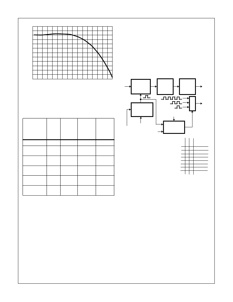
TABLE 10. POLYPHASE AND INTERPOLATING HALFBAND
FILTER MAXIMUM CLOCKING RATES
MODE
CLOCK
CYCLES
RE-SAM-
PLER
INPUT
RATE
(MHz)
INTER-
POLATION
RATE
OUTPUT
RATE
(MHz)
Bypass
0
55.00
-
55.0
Polyphase Filter
6
55/6
= 9.17
-
9.17
(Note 3)
Polyphase and
1 Halfband Filter
13
55/13
= 4.23
2
8.46
(Note 3)
Polyphase and
2HalfbandFilters
23
55/23
= 2.39
4
9.56
(Note 3)
1 Halfband Filter
7
55/7
= 7.86
2
15.71
2HalfbandFilters
17
55/17
= 3.24
4
12.94
NOTE:
3. This frequency is set by the Resampler NCO.
FIGURE 24C. POLYPHASE RESAMPLER FILTER EXPANDED
RESOLUTION PASSBAND FREQUENCY
RESPONSE
2
1
0
-1
-2
-3
-4
-5
-6
-7
-8
-9
-10
M
0
0
0
0
0
0
0
0
0
FREQUENCY (RELATIVE TO f
IN
)
FIGURE 25. GENERATING DATA READY PULSES FOR OUTPUT
DATA
PROCCLK/N
PULSE
DELAY
PROCCLK
H
0
0
0
0
1
1
1
1
3 (NV)
3 (NV)
3
3
H
0
0
1
1
0
0
1
1
R
0
1
0
1
0
1
0
1
# EXTRA
PULSES
0 BYPASS
0
1
1
THIS BLOCK GENERATES EXTRA
DATA READY PULSES FOR THE
NEW OUTPUTS FROM THE
INTERPOLATION PROCESS.
PULSE DELAY
COUNTER
HALFBAND
FILTER #2
HALFBAND
FILTER #1
POLYPHASE
RESAMPLER
FILTER
RESAMPLER
NCO
M
NV = INVALID MODE
HSP50214A
相關(guān)PDF資料 |
PDF描述 |
|---|---|
| HSP50214AVI | Programmable Downconverter |
| HSP50214B | Programmable Downconverter |
| HSP50214BVC | Programmable Downconverter |
| HSP50214BVI | Programmable Downconverter |
| HT84 | ADSL Coupling Transformers |
相關(guān)代理商/技術(shù)參數(shù) |
參數(shù)描述 |
|---|---|
| HSP50214AVI | 制造商:INTERSIL 制造商全稱:Intersil Corporation 功能描述:Programmable Downconverter |
| HSP50214B | 制造商:INTERSIL 制造商全稱:Intersil Corporation 功能描述:Programmable Downconverter |
| HSP50214B_07 | 制造商:INTERSIL 制造商全稱:Intersil Corporation 功能描述:Programmable Downconverter |
| HSP50214BVC | 功能描述:上下轉(zhuǎn)換器 120L MQFP COMTEMP 14-BIT PROGRAMMABLE DOWNCONVERTER 65MSPS RoHS:否 制造商:Texas Instruments 產(chǎn)品:Down Converters 射頻:52 MHz to 78 MHz 中頻:300 MHz LO頻率: 功率增益: P1dB: 工作電源電壓:1.8 V, 3.3 V 工作電源電流:120 mA 最大功率耗散:1 W 最大工作溫度:+ 85 C 安裝風(fēng)格:SMD/SMT 封裝 / 箱體:PQFP-128 |
| HSP50214BVCZ | 功能描述:上下轉(zhuǎn)換器 120L MQFP COMTEMP 14-BIT PROG DWNCNVRT RoHS:否 制造商:Texas Instruments 產(chǎn)品:Down Converters 射頻:52 MHz to 78 MHz 中頻:300 MHz LO頻率: 功率增益: P1dB: 工作電源電壓:1.8 V, 3.3 V 工作電源電流:120 mA 最大功率耗散:1 W 最大工作溫度:+ 85 C 安裝風(fēng)格:SMD/SMT 封裝 / 箱體:PQFP-128 |
發(fā)布緊急采購,3分鐘左右您將得到回復(fù)。