- 您現(xiàn)在的位置:買賣IC網(wǎng) > PDF目錄370213 > FMS988AKAC140 Signal Conditioner PDF資料下載
參數(shù)資料
| 型號(hào): | FMS988AKAC140 |
| 英文描述: | Signal Conditioner |
| 中文描述: | 信號(hào)調(diào)理 |
| 文件頁數(shù): | 6/29頁 |
| 文件大小: | 481K |
| 代理商: | FMS988AKAC140 |
第1頁第2頁第3頁第4頁第5頁當(dāng)前第6頁第7頁第8頁第9頁第10頁第11頁第12頁第13頁第14頁第15頁第16頁第17頁第18頁第19頁第20頁第21頁第22頁第23頁第24頁第25頁第26頁第27頁第28頁第29頁

PRODUCT SPECIFICATION
FMS9875
6
REV. 1.2.15 1/14/02
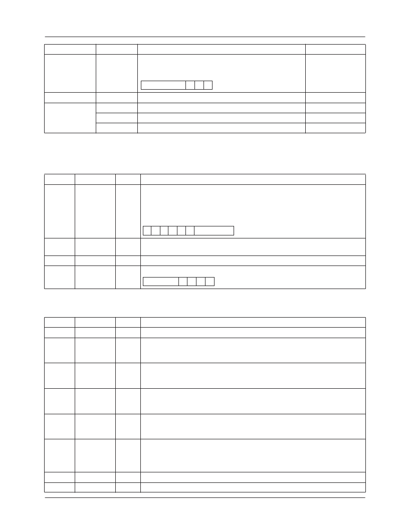
Register Definitions
PLL Control Register (01)
PHASE
7-0
0B
Sampling clock phase.
PHASE
4-0
stored in upper
register bits 7-3. PHASE sets the sampling clock phase in
11.25° increments. Default value is decimal 16.
80
PLLCTRL
CONFIG 2
0C
0D
0E
0F
PLL Control.
Configuration Register No. 2.
Clamp Control Register.
Reserved.
24
00
00
00
Bit no.
1-0
Name
SUBDIV
1-0
Type
R/W
Description
PLL Subdivide ratio.
Selects the ratio of the divider following the PLL.
00:
divide-by 1
01:
divide-by 2
10:
divide-by 4
11:
reserved
2
PLLFAZ
R/W
PLL Sub-divider Phase.
Selects the phase of the divide-by-2 output.
(Invalid for other outputs)
Reserved.
PLL divide ratio, LSBs.
PLLN + 1 = total number of pixels per horizontal line.
3
–
R/W
R/W
7-4
PLLN
3-0
Configuration Register 1 (0A)
Bit no.
0
1
Name
Type
Description
XCKSEL
R/W
External Clock Select.
Select internal clock source.
0:
Internal PLL
1:
XCK input.
External Clamp Polarity.
Select clamp polarity.
0:
Active L.
1:
Active H.
External Clamp Select.
Select clamp source.
0:
Internally generated by PLL referenced to HSIN.
1:
External CLAMP input.
Coast Polarity.
Select COAST input polarity.
0:
Active L.
1:
Active H.
HSIN Polarity.
Select horizontal sync input polarity. PLL is locked to selected
edge:
0:
Falling edge.
1:
Rising edge.
1:
1:
2
XCLAMPOL
R/W
3
XCLAMP
R/W
4
COASTPOL
R/W
5
HSPOL
R/W
6
7
—
—
R
R
Name
Address
Function
Default (hex)
PHASE
4–0
X X X
SUBDIV
1–0
X X X X
PLLN
3–0
X X X
X
X X
相關(guān)PDF資料 |
PDF描述 |
|---|---|
| FMU1 | TRANSISTOR | SOT-143R |
| RU101K | TRANSISTOR | SOT-23 |
| FMU3-48R000 | Logic IC |
| FMU3-48R000M | Logic IC |
| FMU3-60R000 | Logic IC |
相關(guān)代理商/技術(shù)參數(shù) |
參數(shù)描述 |
|---|---|
| FMSA125 | 制造商:MicroSwitch 功能描述:4-DAY SHIPPING -Inductive |
| FMSA-461 | 制造商:INTERPOINT 制造商全稱:INTERPOINT 功能描述:EMI INPUT FILTER 28 VOLT INPUT |
| FMSA-461/883 | 制造商:INTERPOINT 制造商全稱:INTERPOINT 功能描述:EMI INPUT FILTER 28 VOLT INPUT |
| FMS-A-C0 | 制造商:Panduit Corp 功能描述: |
| FMSC1125-W | 制造商:FLORIDA MISC. 功能描述: |
發(fā)布緊急采購,3分鐘左右您將得到回復(fù)。