- 您現(xiàn)在的位置:買賣IC網(wǎng) > PDF目錄378525 > DA28F320S5-90 (INTEL CORP) 16 Characters x 2 Lines, 5x7 Dot Matrix Character and Cursor PDF資料下載
參數(shù)資料
| 型號: | DA28F320S5-90 |
| 廠商: | INTEL CORP |
| 元件分類: | DRAM |
| 英文描述: | 16 Characters x 2 Lines, 5x7 Dot Matrix Character and Cursor |
| 中文描述: | 4M X 8 FLASH 5V PROM, 90 ns, PDSO56 |
| 封裝: | 16 X 23.70 MM, SSOP-56 |
| 文件頁數(shù): | 30/53頁 |
| 文件大小: | 641K |
| 代理商: | DA28F320S5-90 |
第1頁第2頁第3頁第4頁第5頁第6頁第7頁第8頁第9頁第10頁第11頁第12頁第13頁第14頁第15頁第16頁第17頁第18頁第19頁第20頁第21頁第22頁第23頁第24頁第25頁第26頁第27頁第28頁第29頁當前第30頁第31頁第32頁第33頁第34頁第35頁第36頁第37頁第38頁第39頁第40頁第41頁第42頁第43頁第44頁第45頁第46頁第47頁第48頁第49頁第50頁第51頁第52頁第53頁
INTEL StrataFlash MEMORY TECHNOLOGY, 32 AND 64 MBIT
E
30
ADVANCE INFORMATION
A successful set block lock-bit operation requires
that the master lock-bit be zero or, if the master
lock-bit is set, that RP# = V
HH
. If it is attempted with
the master lock-bit set and RP# = V
IH
, SR.1 and
SR.4 will be set to
“1” and the operation will fail. Set
block lock-bit operations while V
IH
< RP# < V
HH
produce spurious results and should not be
attempted. A successful set master lock-bit
operation requires that RP# = V
HH
. If it is attempted
with RP# = V
IH
, SR.1 and SR.4 will be set to “1”
and the operation will fail. Set master lock-bit
operations with V
IH
< RP# < V
HH
produce spurious
results and should not be attempted.
4.12
Clear Block Lock-Bits
Command
All set block lock-bits are cleared in parallel via the
Clear Block Lock-Bits command. With the master
lock-bit not set, block lock-bits can be cleared using
only the Clear Block Lock-Bits command. If the
master lock-bit is set, clearing block lock-bits
requires both the Clear Block Lock-Bits command
and V
HH
on the RP# pin. This command is invalid
while the WSM is running or the device is
suspended. See Table 14 for a summary of
hardware and software write protection options.
Clear block lock-bits command is executed by a
two-cycle sequence. A clear block lock-bits setup is
first written. The device automatically outputs status
register data when read (see Figure 12). The CPU
can detect completion of the clear block lock-bits
event by analyzing the STS pin output or status
register bit SR.7.
When the operation is complete, status register bit
SR.5 should be checked. If a clear block lock-bit
error is detected, the status register should be
cleared. The CUI will remain in read status register
mode until another command is issued.
This two-step sequence of set-up followed by
execution ensures that block lock-bits are not
accidentally cleared. An invalid Clear Block
Lock-Bits command sequence will result in status
register bits SR.4 and SR.5 being set to “1.” Also, a
reliable clear block lock-bits operation can only
occur when V
CC
and V
PEN
are valid. If a clear block
lock-bits operation is attempted while V
PEN
≤
V
PENLK
, SR.3 and SR.5 will be set to “1.” A
successful clear block lock-bits operation requires
that the master lock-bit is not set or, if the master
lock-bit is set, that RP# = V
HH
. If it is attempted with
the master lock-bit set and RP# = V
IH
, SR.1 and
SR.5 will be set to “1” and the operation will fail. A
clear block lock-bits operation with V
IH
< RP# < V
HH
produce spurious results and should not be
attempted.
If a clear block lock-bits operation is aborted due to
V
PEN
or V
CC
transitioning out of valid range or RP#
active transition, block lock-bit values are left in an
undetermined state. A repeat of clear block lock-
bits is required to initialize block lock-bit contents to
known values. Once the master lock-bit is set, it
cannot be cleared.
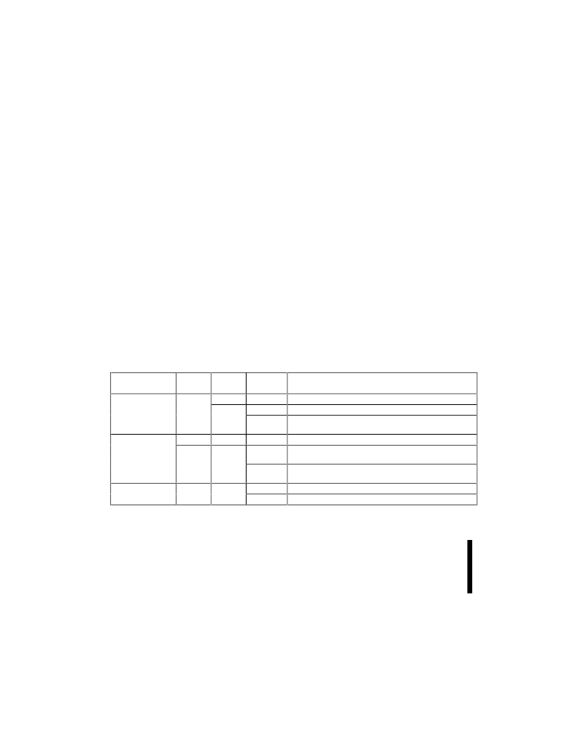
Table 14. Write Protection Alternatives
Operation
Block Erase or
Program
Master
Lock-Bit
Block
Lock-Bit
0
1
RP#
Effect
V
IH
or V
HH
Block Erase and Program Enabled
V
IH
Block is Locked. Block Erase and Program Disabled
V
HH
Block Lock-Bit Override. Block Erase and Program
Enabled
V
IH
or V
HH
Set or Clear Block Lock-Bit Enabled
V
IH
Master Lock-Bit Is Set. Set or Clear Block Lock-Bit
Disabled
V
HH
Master Lock-Bit Override. Set or Clear Block Lock-Bit
Enabled
V
IH
Set Master Lock-Bit Disabled
V
HH
Set Master Lock-Bit Enabled
X
Set or Clear Block
Lock-Bit
0
1
X
X
Set Master
Lock-Bit
X
X
相關PDF資料 |
PDF描述 |
|---|---|
| DA8110A | Rectifier Arrays |
| DA8110K | Rectifier Arrays |
| DA811A | Rectifier Arrays |
| DA811AK | Rectifier Arrays |
| DA811K | Rectifier Arrays |
相關代理商/技術參數(shù) |
參數(shù)描述 |
|---|---|
| DA28F640J5-150 | 制造商:Intel 功能描述: |
| DA28F640J5A-150 | 制造商:INTEL 制造商全稱:Intel Corporation 功能描述:5 Volt Intel StrataFlash? Memory |
| DA29-00003B | 制造商:Samsung Semiconductor 功能描述:Samsung Refrigerator Water Filter |
| DA29-00003BE | 制造商:Samsung Semiconductor 功能描述:Aqua-Pure Replacement Refrigerator Filter 制造商:SAMSUNG GVI 功能描述:SAMSUNG DA29-00003G WATER FILTER |
| DA29-00020B | 制造商:Samsung Semiconductor 功能描述:WATER FILTER |
發(fā)布緊急采購,3分鐘左右您將得到回復。