- 您現(xiàn)在的位置:買賣IC網(wǎng) > PDF目錄379002 > CY22E016L (Cypress Semiconductor Corp.) 16-Kbit (2K x 8) nvSRAM PDF資料下載
參數(shù)資料
| 型號: | CY22E016L |
| 廠商: | Cypress Semiconductor Corp. |
| 英文描述: | 16-Kbit (2K x 8) nvSRAM |
| 中文描述: | 16千位(2K × 8)非易失 |
| 文件頁數(shù): | 4/14頁 |
| 文件大小: | 748K |
| 代理商: | CY22E016L |
PRELIMINARY
CY22E016L
Document #: 001-06727 Rev. *C
Page 4 of 14
In order to prevent unneeded STORE
operations, automatic
STOREs as well as those initiated by externally driving HSB
low will be ignored unless at least one
WRITE
operation has
taken place since the most recent STORE
or RECALL
cycle.
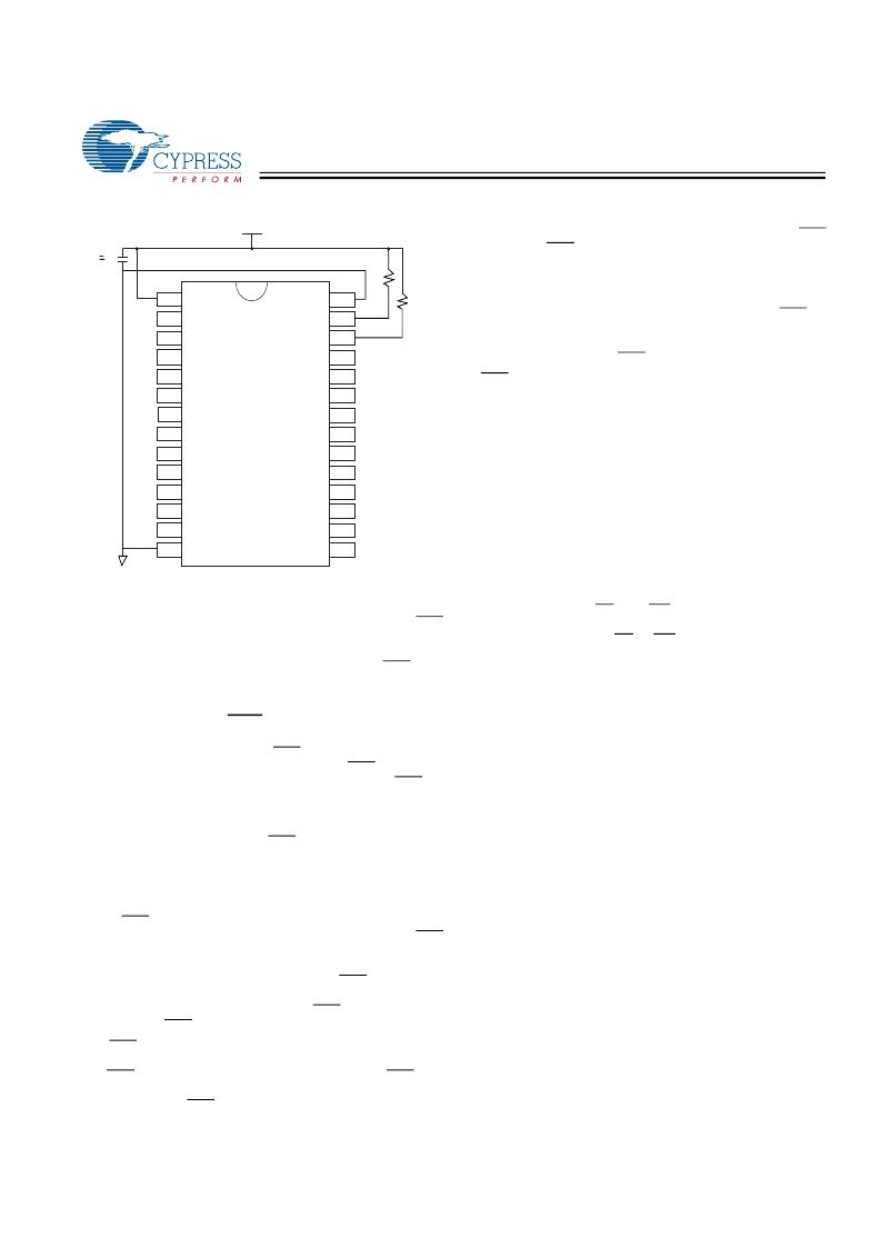
An optional pull-up resistor is shown connected to HSB. This
can be used to signal the system that the AutoStore cycle is in
progress.
Hardware STORE (HSB) Operation
The CY22E016L provides the HSB pin for controlling and
acknowledging the STORE operations. The HSB pin can be
used to request a hardware STORE cycle. When the HSB pin
is driven low, the CY22E016L will conditionally initiate a
STORE operation after t
DELAY
. An actual STORE cycle will
only begin if a WRITE to the SRAM took place since the last
STORE or RECALL cycle. The HSB pin also acts as an open
drain driver that is internally driven low to indicate a busy
condition while the STORE (initiated by any means) is in
progress.
SRAM READ and WRITE operations that are in progress
when HSB is driven low by any means are given time to
complete before the STORE operation is initiated. After HSB
goes low, the CY22E016L will continue SRAM operations for
t
DELAY
. During t
DELAY
, multiple SRAM READ operations may
take place. If a WRITE is in progress when HSB is pulled low
it will be allowed a time, t
DELAY
, to complete. However, any
SRAM WRITE cycles requested after HSB goes low will be
inhibited until HSB returns high.
The HSB pin can be used to synchronize multiple CY22E016L
while using a single larger capacitor. To operate in this mode
the HSB pin should be connected together to the HSB pins
from the other CY22E016L. An external pull-up resistor to +5V
is required since HSB acts as an open-drain pull-down. The
V
CAP
pins from the other CY22E016L parts can be tied
together and share a single capacitor. The capacitor size must
be scaled by the number of devices connected to it. When any
one of the CY22E016L detects a power loss and asserts HSB,
the common HSB pin will cause all parts to request a STORE
cycle (a STORE
will take place in those CY22E016L that have
been written since the last nonvolatile cycle).
During any STORE operation, regardless of how it was
initiated, the CY22E016L will continue to drive the HSB pin
low, releasing it only when the STORE is complete. Upon
completion of the STORE operation the CY22E016L will
remain disabled until the HSB pin returns high.
If HSB is not used, it should be left unconnected.
Hardware RECALL (Power-up)
During power-up, or after any low-power condition (V
CC
<
V
SWITCH
), an internal RECALL request will be latched. When
V
CC
once again exceeds the sense voltage of V
SWITCH
, a
RECALL cycle will automatically be initiated and will take
t
HRECALL
to complete.
Data Protection
The CY22E016L protects data from corruption during
low-voltage conditions by inhibiting all externally initiated
STORE and WRITE operations. The low voltage condition is
detected when V
CC
< V
SWITCH
. If the CY22E016L is in a
WRITE mode (both CE and WE low) at power-up, after a
RECALL, or after a STORE, the WRITE will be inhibited until
a negative transition on CE or WE is detected. This protects
against inadvertent writes during power-up or brown-out
conditions.
Noise Considerations
The CY22E016L is a high-speed memory and so must have a
high-frequency bypass capacitor of approximately 0.1 μF
connected between V
CC
and V
SS
, using leads and traces that
are as short as possible. As with all high-speed CMOS ICs,
careful routing of power, ground, and signals will reduce circuit
noise.
Low Average Active Power
CMOS technology provides the CY22E016L the benefit of
drawing significantly less current when it is cycled at times
longer than 50 ns.
Figure 4
shows the relationship between
I
CC
and READ/WRITE cycle time. Worst-case current
consumption is shown for both CMOS and TTL input levels
(commercial temperature range, VCC = 5.5V, 100% duty cycle
on chip enable). Only standby current is drawn when the chip
is disabled. The overall average current drawn by the
CY22E016L depends on the following items:
1. The duty cycle of chip enable.
2. The overall cycle rate for accesses.
3. The ratio of READs to WRITEs.
4. CMOS vs. TTL Input Levels.
5. The operating temperature.
6. The V
CC
level.
7. I/O loading.
Figure 3. AutoStore Inhibit Mode
28
1
1
1
27
26
14
15
0
U
B
[+] Feedback
相關PDF資料 |
PDF描述 |
|---|---|
| CY22E016L-SZ25XCT | 16-Kbit (2K x 8) nvSRAM |
| CY22E016L-SZ35XCT | 16-Kbit (2K x 8) nvSRAM |
| CY22E016L-SZ35XIT | 16-Kbit (2K x 8) nvSRAM |
| CY22E016L-SZ45XCT | 16-Kbit (2K x 8) nvSRAM |
| CY2313ANZSC-1 | 13 Output, 3.3V SDRAM Buffer for Desktop PCs with 3 DIMMs |
相關代理商/技術參數(shù) |
參數(shù)描述 |
|---|---|
| CY22E016L_07 | 制造商:CYPRESS 制造商全稱:Cypress Semiconductor 功能描述:16 Kbit (2K x 8) nvSRAM |
| CY22E016L-SZ25XC | 制造商:Cypress Semiconductor 功能描述: |
| CY22E016L-SZ25XCT | 制造商:CYPRESS 制造商全稱:Cypress Semiconductor 功能描述:16 Kbit (2K x 8) nvSRAM |
| CY22E016L-SZ25XI | 制造商:CYPRESS 制造商全稱:Cypress Semiconductor 功能描述:16 Kbit (2K x 8) nvSRAM |
| CY22E016L-SZ25XIT | 制造商:CYPRESS 制造商全稱:Cypress Semiconductor 功能描述:16 Kbit (2K x 8) nvSRAM |
發(fā)布緊急采購,3分鐘左右您將得到回復。