- 您現(xiàn)在的位置:買賣IC網(wǎng) > PDF目錄370013 > PowerPC 750CX (IBM Microeletronics) 32-Bit Reduced Instruction Set Computer (RISC) Microprocessors(32位精簡指令集微處理器) PDF資料下載
參數(shù)資料
| 型號: | PowerPC 750CX |
| 廠商: | IBM Microeletronics |
| 英文描述: | 32-Bit Reduced Instruction Set Computer (RISC) Microprocessors(32位精簡指令集微處理器) |
| 中文描述: | 32位精簡指令集計(jì)算機(jī)(RISC)微處理器(32位精簡指令集微處理器) |
| 文件頁數(shù): | 39/44頁 |
| 文件大?。?/td> | 562K |
| 代理商: | POWERPC 750CX |
第1頁第2頁第3頁第4頁第5頁第6頁第7頁第8頁第9頁第10頁第11頁第12頁第13頁第14頁第15頁第16頁第17頁第18頁第19頁第20頁第21頁第22頁第23頁第24頁第25頁第26頁第27頁第28頁第29頁第30頁第31頁第32頁第33頁第34頁第35頁第36頁第37頁第38頁當(dāng)前第39頁第40頁第41頁第42頁第43頁第44頁

PowerPC 750CX RISC Microprocessor Datasheet
November 13, 2000
Version 1.1
Page 39
7.9.4 DBWO/L2_TSTCLK
One pin has two functions: DBWO and L2_TSTCLK dependent upon the LSSD_MODE pin. When the LSSD_MODE
pin is low, the DBWO/L2_TSTCLK pin is set to L2_TSTCLK function which is used during the manufacturing process
for testing.
When the LSSD_MODE pin is pulled to the high state, the DBWO/L2_TSTCLK pin is set to DBWO which is identical
to those descriptions given in earlier versions of the PowerPC 750CX RISC Microprocessor’s User’s Manuals.
7.9.5 PowerPC 750CX Revision Level Migration
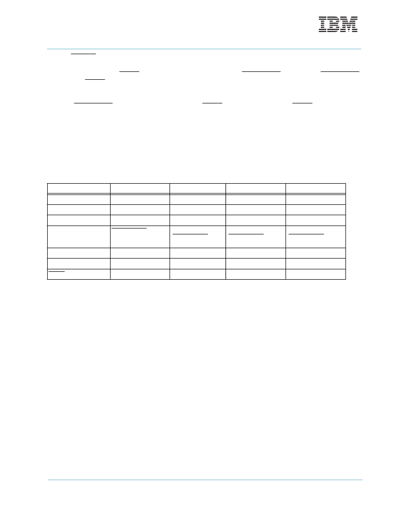
The following table summarizes the design changes for the respective PowerPC 750CX design revision lev-
els.
8.0 Ordering Information
This section provides the part numbering nomenclature for the PowerPC 750CX. Note that the individual part numbers
correspond to a maximum processor core frequency. For available frequencies, contact your local IBM sales office.
In addition to the processor frequency and bus ratio, the part numbering scheme also consists of a part modifier. The part
modifier allows for the availability of future enhanced parts (i.e., lower voltage, lower power, higher performance, etc.).
Each part number also contains a revision code. This refers to the die mask revision number and is specified in the part
numbering scheme for identification purposes only.
Figure 19 provides the IBM part numbering nomenclature for the PowerPC 750CX.
Table 17: Summary of Design Migration
DD1.0
DD2.0
DD2.1
DD2.2
PVR
0x00080100
0x00080100
0x00082201
0x00082202
L1 Data Bus Width
64-Bits
256-Bits
256-Bits
256-Bits
DPM
Enabled
Disabled
Disabled
Disabled
Test Pin
CHKSTP_OUT removed
CLKOUT/
CHKSTP_OUT share
a pin
CLKOUT/
CHKSTP_OUT share a
pin
CLKOUT/
CHKSTP_OUT share a
pin
32-Bit Mode
Not available
Available
Available
Available
Floating Bus
Pull-ups required
No pull-ups
No pull-ups
No pull-ups
DBWO Pin
Absent
Absent
Present
Present
相關(guān)PDF資料 |
PDF描述 |
|---|---|
| PowerPC 750 | 32-Bit Embedded Microprocessor(32位精簡指令集嵌入式微處理器) |
| PP-MOD1V2 | ISP INTERFACE MODULE |
| PP01002 | GEHOERSCHUTZ OHRSTOEPSEL 250ST Inhalt pro Packung: 250 Stk. |
| PP0901SA | Direct ProTek Replacement:PP0901SA |
| PP0901SB | Direct ProTek Replacement:PP0901SB |
相關(guān)代理商/技術(shù)參數(shù) |
參數(shù)描述 |
|---|---|
| POWERPLUG15W | 制造商:STMICROELECTRONICS 制造商全稱:STMicroelectronics 功能描述:AC/DC POWER SUPPLY |
| POWERPLUG24W | 制造商:STMICROELECTRONICS 制造商全稱:STMicroelectronics 功能描述:AC/DC POWER SUPPLY |
| POWERPLUS 2C 2500MAH | 制造商:Energizer Battery Company 功能描述: |
| POWERPLUS 2D 2500MAH | 制造商:Energizer Battery Company 功能描述: |
| POWERPLUS 4AAA 850MAH | 制造商:Energizer Battery Company 功能描述: |
發(fā)布緊急采購,3分鐘左右您將得到回復(fù)。