- 您現(xiàn)在的位置:買(mǎi)賣(mài)IC網(wǎng) > PDF目錄370013 > PowerPC 750CX (IBM Microeletronics) 32-Bit Reduced Instruction Set Computer (RISC) Microprocessors(32位精簡(jiǎn)指令集微處理器) PDF資料下載
參數(shù)資料
| 型號(hào): | PowerPC 750CX |
| 廠(chǎng)商: | IBM Microeletronics |
| 英文描述: | 32-Bit Reduced Instruction Set Computer (RISC) Microprocessors(32位精簡(jiǎn)指令集微處理器) |
| 中文描述: | 32位精簡(jiǎn)指令集計(jì)算機(jī)(RISC)微處理器(32位精簡(jiǎn)指令集微處理器) |
| 文件頁(yè)數(shù): | 17/44頁(yè) |
| 文件大?。?/td> | 562K |
| 代理商: | POWERPC 750CX |
第1頁(yè)第2頁(yè)第3頁(yè)第4頁(yè)第5頁(yè)第6頁(yè)第7頁(yè)第8頁(yè)第9頁(yè)第10頁(yè)第11頁(yè)第12頁(yè)第13頁(yè)第14頁(yè)第15頁(yè)第16頁(yè)當(dāng)前第17頁(yè)第18頁(yè)第19頁(yè)第20頁(yè)第21頁(yè)第22頁(yè)第23頁(yè)第24頁(yè)第25頁(yè)第26頁(yè)第27頁(yè)第28頁(yè)第29頁(yè)第30頁(yè)第31頁(yè)第32頁(yè)第33頁(yè)第34頁(yè)第35頁(yè)第36頁(yè)第37頁(yè)第38頁(yè)第39頁(yè)第40頁(yè)第41頁(yè)第42頁(yè)第43頁(yè)第44頁(yè)

PowerPC 750CX RISC Microprocessor Datasheet
November 13, 2000
Version 1.1
Page 17
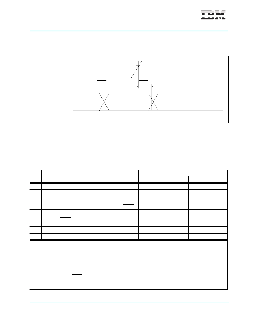
Figure 4 provides the mode select input timing diagram for the PowerPC 750CX.
5.4
60X Bus Output AC Specifications
Table 8 provides the 60X bus output AC timing specifications for the PowerPC 750CX as defined in Figure 6 on
page 19.
Figure 4. Mode Select Input Timing Diagram
Table 8: 60X Bus Output AC Timing Specifications
1,4,6,7
See Table 2 on page 12 for operating conditions.
Num
Characteristic
1.8V Mode
2.5V Mode
Unit
Notes
Min.
Max.
Min.
Max.
12
SYSCLK to Output Driven (Output Enable Time)
0.3
0.3
ns
13
SYSCLK to Output Valid
–
2.31
–
2.61
ns
14
SYSCLK to Output Invalid (Output Hold)
0.400
0.400
ns
2
15
SYSCLK to Output High Impedance (all signals except ARTRY)
–
2.5
–
2.5
ns
16
SYSCLK to ARTRY high impedance before precharge
–
3.0
–
3.0
ns
17
SYSCLK to ARTRY precharge enable
0.2
×
t
+ 1.0
0.2
×
t
+ 1.0
ns
2, 3, 5
18
Maximum delay to ARTRY precharge
1
1
t
SYSCLK
3, 5
19
SYSCLK to ARTRY high impedance after precharge
2
2
t
SYSCLK
3, 5
Note:
1. All output specifications are measured from the midpoint voltage (0.8V) of the rising edge of SYSCLK to the midpoint voltage of the signal in question
defined in figure 5. Both input and output timings are measured at the pin. Timings are determined by design.
2. This minimum parameter assumes CL = 0pF.
3. t
is the period of the external bus clock (SYSCLK) in nanoseconds (ns). The numbers given in the table must be multiplied by the period of
SYSCLK to compute the actual time duration of the parameter in question.
4. Output signal transitions are defined in figure 5.
5. Nominal precharge width for ARTRY is 1.0 t
SYSCLK
.
6. Guaranteed by design and characterization, and not tested.
7. These timings are valid for processors up to 466MHz. 500MHz processor timing behavior and characterization are being evaluated at this time.
V
IH
V
IH
= 1.24V
MODE PINS
10c
11b
HRESET
10c
11b
相關(guān)PDF資料 |
PDF描述 |
|---|---|
| PowerPC 750 | 32-Bit Embedded Microprocessor(32位精簡(jiǎn)指令集嵌入式微處理器) |
| PP-MOD1V2 | ISP INTERFACE MODULE |
| PP01002 | GEHOERSCHUTZ OHRSTOEPSEL 250ST Inhalt pro Packung: 250 Stk. |
| PP0901SA | Direct ProTek Replacement:PP0901SA |
| PP0901SB | Direct ProTek Replacement:PP0901SB |
相關(guān)代理商/技術(shù)參數(shù) |
參數(shù)描述 |
|---|---|
| POWERPLUG15W | 制造商:STMICROELECTRONICS 制造商全稱(chēng):STMicroelectronics 功能描述:AC/DC POWER SUPPLY |
| POWERPLUG24W | 制造商:STMICROELECTRONICS 制造商全稱(chēng):STMicroelectronics 功能描述:AC/DC POWER SUPPLY |
| POWERPLUS 2C 2500MAH | 制造商:Energizer Battery Company 功能描述: |
| POWERPLUS 2D 2500MAH | 制造商:Energizer Battery Company 功能描述: |
| POWERPLUS 4AAA 850MAH | 制造商:Energizer Battery Company 功能描述: |
發(fā)布緊急采購(gòu),3分鐘左右您將得到回復(fù)。