- 您現(xiàn)在的位置:買賣IC網(wǎng) > PDF目錄359243 > MVTX2604 (Zarlink Semiconductor Inc.) Managed 24-Port 10/100 Mb + 2 Port 1 Gb Ethernet Switch PDF資料下載
參數(shù)資料
| 型號: | MVTX2604 |
| 廠商: | Zarlink Semiconductor Inc. |
| 英文描述: | Managed 24-Port 10/100 Mb + 2 Port 1 Gb Ethernet Switch |
| 中文描述: | 管理24端口的10/100 Mb 2端口千兆以太網(wǎng)交換機1 |
| 文件頁數(shù): | 28/173頁 |
| 文件大小: | 2097K |
| 代理商: | MVTX2604 |
第1頁第2頁第3頁第4頁第5頁第6頁第7頁第8頁第9頁第10頁第11頁第12頁第13頁第14頁第15頁第16頁第17頁第18頁第19頁第20頁第21頁第22頁第23頁第24頁第25頁第26頁第27頁當(dāng)前第28頁第29頁第30頁第31頁第32頁第33頁第34頁第35頁第36頁第37頁第38頁第39頁第40頁第41頁第42頁第43頁第44頁第45頁第46頁第47頁第48頁第49頁第50頁第51頁第52頁第53頁第54頁第55頁第56頁第57頁第58頁第59頁第60頁第61頁第62頁第63頁第64頁第65頁第66頁第67頁第68頁第69頁第70頁第71頁第72頁第73頁第74頁第75頁第76頁第77頁第78頁第79頁第80頁第81頁第82頁第83頁第84頁第85頁第86頁第87頁第88頁第89頁第90頁第91頁第92頁第93頁第94頁第95頁第96頁第97頁第98頁第99頁第100頁第101頁第102頁第103頁第104頁第105頁第106頁第107頁第108頁第109頁第110頁第111頁第112頁第113頁第114頁第115頁第116頁第117頁第118頁第119頁第120頁第121頁第122頁第123頁第124頁第125頁第126頁第127頁第128頁第129頁第130頁第131頁第132頁第133頁第134頁第135頁第136頁第137頁第138頁第139頁第140頁第141頁第142頁第143頁第144頁第145頁第146頁第147頁第148頁第149頁第150頁第151頁第152頁第153頁第154頁第155頁第156頁第157頁第158頁第159頁第160頁第161頁第162頁第163頁第164頁第165頁第166頁第167頁第168頁第169頁第170頁第171頁第172頁第173頁
MVTX2604
Data Sheet
30
Zarlink Semiconductor Inc.
5.7 Port and Tag Based VLAN
The MVTX2604 supports two models for determining and controlling how a packet gets assigned to a VLAN: port
priority and tag -based VLAN.
5.7.1 Port-Based VLAN
An administrator can use the PVMAP Registers to configure the MVTX2604 for port-based VLAN (see “Registration
Definition” on page 42). For example, ports 1-3 might be assigned to the Marketing VLAN, ports 4-6 to the
Engineering VLAN and ports 7-9 to the Administrative VLAN. The MVTX2604 determines the VLAN membership of
each packet by noting the port on which it arrives. From there, the MVTX2604 determines which outgoing port(s)
is/are eligible to transmit each packet or whether the packet should be discarded.
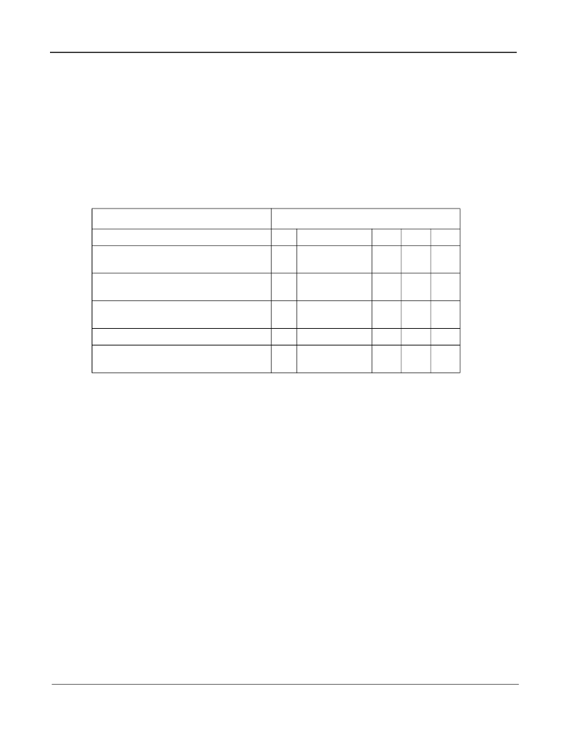
Table 3 - PVMAP Register
For example, in the above table, a "1" denotes that an outgoing port is eligible to receive a packet from an incoming
port. A 0 (zero) denotes that an outgoing port is not eligible to receive a packet from an incoming port.
In this example:
Data packets received at port #0 are eligible to be sent to outgoing ports 1 and 2.
Data packets received at port #1 are eligible to be sent to outgoing ports 0 and 2.
Data packets received at port #2 are
NOT
eligible to be sent to ports 0 and 1.
5.7.2 Tag-Based VLAN
The MVTX2604 supports the IEEE 802.1q specification for “tagging” frames. The specification defines a way to
coordinate VLANs across multiple switches. In the specification, an additional 4-octet header (or “tag”) is inserted in
a frame after the source MAC address and before the frame type. 12 bits of the tag are used to define the VLAN ID.
Packets are then switched through the network with each MVTX2604 simply swapping the incoming tag for an
appropriate forwarding tag rather than processing each packet's contents to determine the path. This approach
minimizes the processing needed once the packet enters the tag-switched network. In addition, coordinating VLAN
IDs across multiple switches enables VLANs to extend to multiple switches.
Up to 255 VLANs are supported in the MVTX2604. The 4 K VLANs specified in the IEEE 802.1q are mapped to 255
VLAN indexes. The mapping is made by the VLAN index mapping table. Based on the VLAN index (VIXn), the
source and destination port membership is checked against the content in the VLAN Index Port association table. If
the destination port is a member of the VLAN, the packet is forwarded; otherwise it is discarded. If the source port is
not a member, a “New VLAN Port” message is sent to the CPU. A filter can be applied to discard the packet if the
source port is not a member of the VLAN.
Destination Port Numbers Bit Map
Port Registers
26
…
2
1
0
Register for Port #0
PVMAP00_0[7:0] to PVMAP00_3[2:0]
0
1
1
0
Register for Port #1
PVMAP01_0[7:0] to PVMAP01_3[2:0]
0
1
0
1
Register for Port #2
PVMAP02_0[7:0] to PVMAP02_3[2:0]
0
0
0
0
…
Register for Port #26
PVMAP26_0[7:0] to PVMAP26_3[2:0]
0
0
0
0
相關(guān)PDF資料 |
PDF描述 |
|---|---|
| MVTX2604AG | Managed 24-Port 10/100 Mb + 2 Port 1 Gb Ethernet Switch |
| MVTX2801 | Unmanaged 4-Port 1000 Mbps Ethernet Switch |
| MVTX2801AG | Unmanaged 4-Port 1000 Mbps Ethernet Switch |
| MVTX2802 | Managed 4-Port 1000 Mbps Ethernet Switch |
| MVTX2802AG | Managed 4-Port 1000 Mbps Ethernet Switch |
相關(guān)代理商/技術(shù)參數(shù) |
參數(shù)描述 |
|---|---|
| MVTX2604A | 制造商:未知廠家 制造商全稱:未知廠家 功能描述:MVTX260x Physical Port Control |
| MVTX2604AG | 制造商:ZARLINK 制造商全稱:Zarlink Semiconductor Inc 功能描述:Managed 24-Port 10/100 Mb + 2 Port 1 Gb Ethernet Switch |
| MVTX2801 | 制造商:ZARLINK 制造商全稱:Zarlink Semiconductor Inc 功能描述:Unmanaged 4-Port 1000 Mbps Ethernet Switch |
| MVTX2801A | 制造商:未知廠家 制造商全稱:未知廠家 功能描述:Unmanaged 4 port Gigabit Ethernet switch |
| MVTX2801AG | 制造商:ZARLINK 制造商全稱:Zarlink Semiconductor Inc 功能描述:Unmanaged 4-Port 1000 Mbps Ethernet Switch |
發(fā)布緊急采購,3分鐘左右您將得到回復(fù)。