- 您現(xiàn)在的位置:買賣IC網(wǎng) > PDF目錄359235 > MT9196AE1 (ZARLINK SEMICONDUCTOR INC) Integrated Digital Phone Circuit (IDPC) PDF資料下載
參數(shù)資料
| 型號(hào): | MT9196AE1 |
| 廠商: | ZARLINK SEMICONDUCTOR INC |
| 元件分類: | 通信及網(wǎng)絡(luò) |
| 英文描述: | Integrated Digital Phone Circuit (IDPC) |
| 中文描述: | SPECIALTY TELECOM CIRCUIT, PDIP28 |
| 封裝: | 0.600 INCH, LEAD FREE, PLASTIC, MS-011AB, DIP-28 |
| 文件頁數(shù): | 16/46頁 |
| 文件大小: | 631K |
| 代理商: | MT9196AE1 |
第1頁第2頁第3頁第4頁第5頁第6頁第7頁第8頁第9頁第10頁第11頁第12頁第13頁第14頁第15頁當(dāng)前第16頁第17頁第18頁第19頁第20頁第21頁第22頁第23頁第24頁第25頁第26頁第27頁第28頁第29頁第30頁第31頁第32頁第33頁第34頁第35頁第36頁第37頁第38頁第39頁第40頁第41頁第42頁第43頁第44頁第45頁第46頁

MT9196
Data Sheet
16
Zarlink Semiconductor Inc.
For ST-BUS mode the configuration of bits 0 to 3, at address 12h, defines both the source of transmit audio and the
B-Channel destination. The configuration of this register permits selection of only one transmit B-Channel at a time.
If no valid transmit path has been selected, via the Transmit Path Selection Register, for a particular B-Channel
then that timeslot output on DSTo is tri-stated.
When a valid receive path has been selected, via the Receive Path Selection Register (address 13h), the active
receive B-Channel is governed by the state of the B2/B1 control bit in Control register 1 (address 0Eh).
Refer to the Path Selection section for detailed information.
SSI Mode
The SSI BUS consists of input and output serial data streams named Din and Dout respectively, a Clock input
signal (CLOCKin), and a framing strobe input (STB). A 4.096 MHz master clock, at CLOCKin, is required for SSI
operation if the bit clock is less than 512 kHz. The timing requirements for SSI are shown in Figures 13 and 14.
In SSI mode the IDPC supports only B-Channel operation. The internal C and D Channel registers used in ST-BUS
mode are not functional for SSI operation. The control bit B2/B1, as described in the ST-BUS section, is ignored
since the B-Channel timeslot is defined by the input STB strobe. Hence, in SSI mode transmit and receive B-
Channel data are always in the channel defined by the STB input.
The data strobe input STB determines the 8-bit timeslot used by the device for both transmit and receive data. This
is an active high signal with an 8 kHz repetition rate.
SSI operation is separated into two categories based upon the serial data rate. If the bit clock is 512 kHz or greater
then the bit clock is used directly by the internal IDPC functions allowing synchronous operation. In this case, the bit
clock is connected directly to the CLOCKin pin while XSTAL2 is left unconnected. If the available bit clock rate is
128 kHz or 256 kHz then a 4096 kHz master clock is required to derive clocks for the internal IDPC functions. If this
clock is available externally then it may be applied directly to the CLOCKin pin. If a 4096 kHz clock is not available
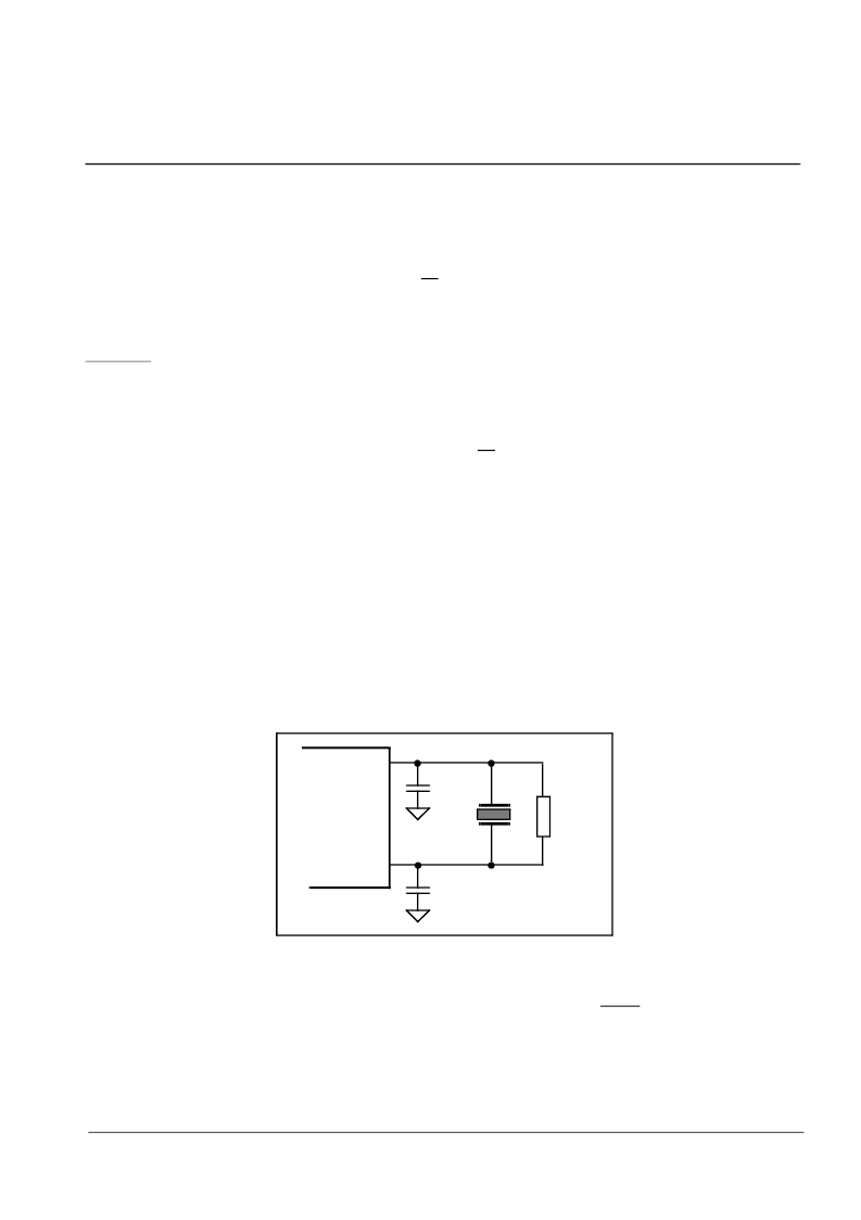
then provision is made to connect a 4096 kHz crystal across the CLOCKin and XSTAL2 pins as shown in Figure 9.
The oscillator circuit has been designed to require an external feedback resistor and load capacitors. This
configuration allows normal ST-BUS operation and synchronous SSI operation with clocks which are not loaded by
these extra components.
Figure 9 - External Crystal Circuit
(for asynchronous operation)
Applications where the bit clock rate is below 512 kHz are designated as asynchronous. The IDPC will generate
and re-align its internal clocks to allow operation when the external master and bit clocks are asynchronous. In this
case, the external bit clock is not connected to the IDPC. Control bits Asynch/Synch, CSL1 and CSL0 in FDI
Control Register (address 10h) are used to program the bit rates as shown in Table 3.
CLOCKin
XSTL2
33 pF
33 pF
100 k
4096 kHz
Nominal
相關(guān)PDF資料 |
PDF描述 |
|---|---|
| MT92220 | 1023 Channel Voice Over IP/AAL2 Processor |
| MT9300B | Multi-Channel Voice Echo Canceller |
| MT9300BL | Multi-Channel Voice Echo Canceller |
| MT9300BV | Multi-Channel Voice Echo Canceller |
| MT9315 | CMOS Acoustic Echo Canceller |
相關(guān)代理商/技術(shù)參數(shù) |
參數(shù)描述 |
|---|---|
| MT9196AP | 制造商:Microsemi Corporation 功能描述: |
| MT9196AP1 | 制造商:Microsemi Corporation 功能描述:INTEGRATED DGTL PHONE CIRCUIT (IDPC) 28PLCC - Rail/Tube 制造商:MICROSEMI CONSUMER MEDICAL PRODUCT GROUP 功能描述:IC DGTL TELEPHONE CIRCUIT 28PLCC 制造商:Microsemi Corporation 功能描述:IC DGTL TELEPHONE CIRCUIT 28PLCC |
| MT9196APR | 制造商:ZARLINK 制造商全稱:Zarlink Semiconductor Inc 功能描述:Integrated Digital Phone Circuit (IDPC) |
| MT9196APR1 | 制造商:Microsemi Corporation 功能描述:INTEGRATED DGTL PHONE CIRCUIT (IDPC) 28PLCC - Tape and Reel 制造商:MICROSEMI CONSUMER MEDICAL PRODUCT GROUP 功能描述:IC DGTL TELEPHONE CIRCUIT 28PLCC 制造商:Microsemi Corporation 功能描述:IC DGTL TELEPHONE CIRCUIT 28PLCC |
| MT9196AS | 制造商:Microsemi Corporation 功能描述: |
發(fā)布緊急采購,3分鐘左右您將得到回復(fù)。