- 您現(xiàn)在的位置:買賣IC網(wǎng) > PDF目錄369889 > M68HC000 (Motorola, Inc.) 16-/32-Bit Microprocessor(16/32位微處理器) PDF資料下載
參數(shù)資料
| 型號: | M68HC000 |
| 廠商: | Motorola, Inc. |
| 英文描述: | 16-/32-Bit Microprocessor(16/32位微處理器) |
| 中文描述: | 16/32位微處理器(16/32位微處理器) |
| 文件頁數(shù): | 155/184頁 |
| 文件大?。?/td> | 1006K |
| 代理商: | M68HC000 |
第1頁第2頁第3頁第4頁第5頁第6頁第7頁第8頁第9頁第10頁第11頁第12頁第13頁第14頁第15頁第16頁第17頁第18頁第19頁第20頁第21頁第22頁第23頁第24頁第25頁第26頁第27頁第28頁第29頁第30頁第31頁第32頁第33頁第34頁第35頁第36頁第37頁第38頁第39頁第40頁第41頁第42頁第43頁第44頁第45頁第46頁第47頁第48頁第49頁第50頁第51頁第52頁第53頁第54頁第55頁第56頁第57頁第58頁第59頁第60頁第61頁第62頁第63頁第64頁第65頁第66頁第67頁第68頁第69頁第70頁第71頁第72頁第73頁第74頁第75頁第76頁第77頁第78頁第79頁第80頁第81頁第82頁第83頁第84頁第85頁第86頁第87頁第88頁第89頁第90頁第91頁第92頁第93頁第94頁第95頁第96頁第97頁第98頁第99頁第100頁第101頁第102頁第103頁第104頁第105頁第106頁第107頁第108頁第109頁第110頁第111頁第112頁第113頁第114頁第115頁第116頁第117頁第118頁第119頁第120頁第121頁第122頁第123頁第124頁第125頁第126頁第127頁第128頁第129頁第130頁第131頁第132頁第133頁第134頁第135頁第136頁第137頁第138頁第139頁第140頁第141頁第142頁第143頁第144頁第145頁第146頁第147頁第148頁第149頁第150頁第151頁第152頁第153頁第154頁當(dāng)前第155頁第156頁第157頁第158頁第159頁第160頁第161頁第162頁第163頁第164頁第165頁第166頁第167頁第168頁第169頁第170頁第171頁第172頁第173頁第174頁第175頁第176頁第177頁第178頁第179頁第180頁第181頁第182頁第183頁第184頁

MOTOROLA
M68000 8-/16-/32-BIT MICROPROCESSORS USER'S MANUAL
10-15
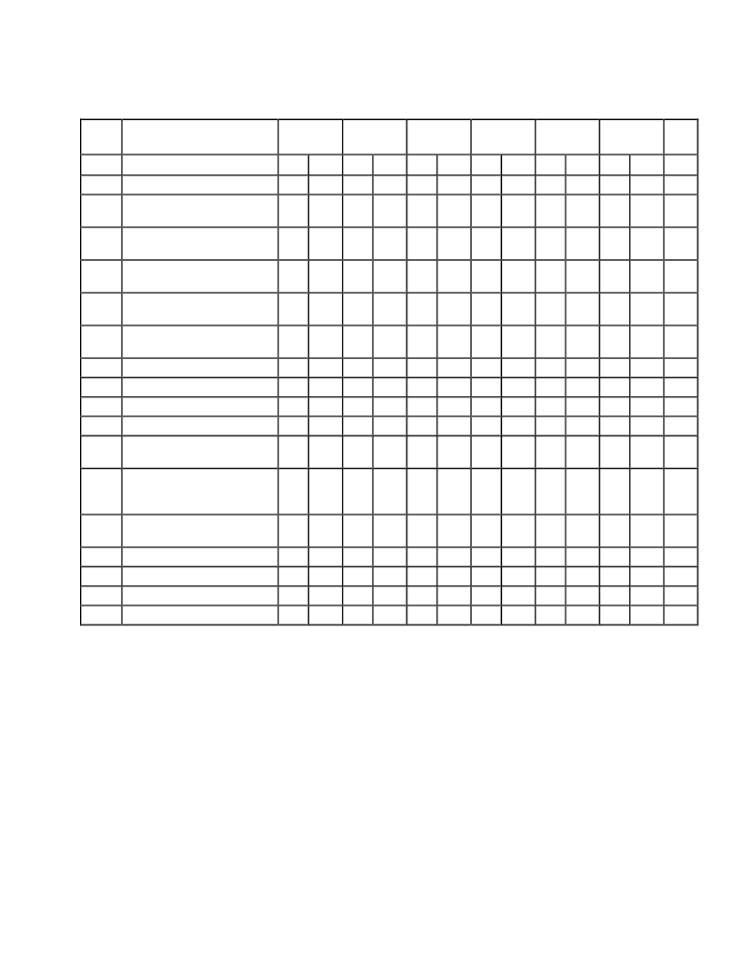
10.11 AC ELECTRICAL SPECIFICATIONS—MC68000 TO M6800
PERIPHERAL
(V
CC
= 5.0 Vdc
±
5%; GND=0 Vdc; T
A
= T
L
TO T
H
; refer to figures 10-6)
(Applies To All Processors Except The MC68EC000)
Num
Characteristic
8 MHz*
10 MHz*
12.5 MHz*
16.67 MHz
`12F'
16 MHz
20 MHz
Unit
Min
Max
Min
Max
Min
Max
Min
Max
Min
Max
Min
Max
121
181
Clock Low to
AS, DS
Negated
—
62
—
50
—
40
—
40
3
30
3
25
ns
Clock High to R/
W
High
(Read)
0
55
0
45
0
40
0
40
0
30
0
25
ns
201
Clock High to R/
W
Low
(Write)
0
55
0
45
0
40
0
40
0
30
0
25
ns
23
Clock Low to Data-Out Valid
(Write)
—
62
—
50
—
50
—
50
—
30
—
25
ns
27
Data-In Valid to Clock Low
(Setup Time on Read)
10
—
10
—
10
—
7
—
5
—
5
—
ns
29
AS, DS
Negated to Data-In
Invalid (Hold Time on Read)
0
—
0
—
0
—
0
—
0
—
0
—
ns
40
Clock Low to
VMA
Asserted
—
70
—
70
—
70
—
50
—
50
—
40
ns
41
Clock Low to E Transition
—
55
—
45
—
35
—
35
—
35
—
30
ns
42
E Output Rise and Fall Time
—
15
—
15
—
15
—
15
—
15
—
12
ns
43
VMA
Asserted to E High
200
—
150
—
90
—
80
—
80
—
60
—
ns
44
AS, DS
Negated to
VPA
Negated
0
120
0
90
0
70
0
50
0
50
0
42
ns
45
E Low to Control, Address
Bus Invalid (Address Hold
Time)
30
—
10
—
10
—
10
—
10
—
10
—
ns
47
Asynchronous Input Setup
Time
10
—
10
—
10
—
10
—
10
—
5
—
ns
492
AS, DS
, Negated to E Low
-70
70
-55
55
-45
45
-35
35
-35
35
–30
30
ns
50
E Width High
450
—
350
—
280
—
220
—
220
—
190
—
ns
51
E Width Low
700
—
550
—
440
—
340
—
340
—
290
—
ns
54
E Low to Data-Out Invalid
30
—
20
—
15
—
10
—
10
—
5
—
ns
*These specifications represent improvement over previously published specifications for the 8-, 10-, and 12.5-MHz
MC68000 and are valid only for product bearing date codes of 8827 and later.
** This frequency applies only to MC68HC000 and MC68HC001.
NOTES:
1. For a loading capacitance of less than or equal to 50 pF, subtract 5 ns from the value given in the
maximum columns.
2. The falling edge of S6 triggers both the negation of the strobes (
AS
and
DS
) and the falling edge of E.
Either of these events can occur first, depending upon the loading on each signal. Specificaton
#49 indicates the absolute maximum skew that will occur between the rising edge of the strobes and the
falling edge of the E clock.
相關(guān)PDF資料 |
PDF描述 |
|---|---|
| M68HC001 | 16-/32-Bit Microprocessor(16/32位微處理器) |
| M68EC000 | 16/32 Bit Microprocesso(16/32位微處理器) |
| M68HC16 | 16-Bit Microcontroller(16位微控制器) |
| MAC08BT1 | TRIAC 0.8 AMPERE RMS 200 thru 600 Volts |
| MAC08MT1 | SENSITIVE GATE TRIACS |
相關(guān)代理商/技術(shù)參數(shù) |
參數(shù)描述 |
|---|---|
| M68HC05 | 制造商:FREESCALE 制造商全稱:Freescale Semiconductor, Inc 功能描述:Microcontrollers |
| M68HC05_13 | 制造商:FREESCALE 制造商全稱:Freescale Semiconductor, Inc 功能描述:M68HC05 Microcontrollers |
| M68HC05EVS | 制造商:MOTOROLA 制造商全稱:Motorola, Inc 功能描述:Motorola M68HC05 Family Evaluation System |
| M68HC05M68H | 制造商:MOTOROLA 制造商全稱:Motorola, Inc 功能描述:HCMOS Microcontroller Unit |
| M68HC08 | 制造商:FREESCALE 制造商全稱:Freescale Semiconductor, Inc 功能描述:Microcontrollers |
發(fā)布緊急采購,3分鐘左右您將得到回復(fù)。