- 您現(xiàn)在的位置:買賣IC網(wǎng) > PDF目錄369885 > LXT388LE PCM TRANSCEIVER|DUAL|CEPT PCM-30/E-1|CMOS|QFP|100PIN|PLASTIC PDF資料下載
參數(shù)資料
| 型號(hào): | LXT388LE |
| 英文描述: | PCM TRANSCEIVER|DUAL|CEPT PCM-30/E-1|CMOS|QFP|100PIN|PLASTIC |
| 中文描述: | 的PCM收發(fā)器|雙|優(yōu)稅PCM-30/E-1 |的CMOS | QFP封裝| 100引腳|塑料 |
| 文件頁數(shù): | 41/80頁 |
| 文件大?。?/td> | 1112K |
| 代理商: | LXT388LE |
第1頁第2頁第3頁第4頁第5頁第6頁第7頁第8頁第9頁第10頁第11頁第12頁第13頁第14頁第15頁第16頁第17頁第18頁第19頁第20頁第21頁第22頁第23頁第24頁第25頁第26頁第27頁第28頁第29頁第30頁第31頁第32頁第33頁第34頁第35頁第36頁第37頁第38頁第39頁第40頁當(dāng)前第41頁第42頁第43頁第44頁第45頁第46頁第47頁第48頁第49頁第50頁第51頁第52頁第53頁第54頁第55頁第56頁第57頁第58頁第59頁第60頁第61頁第62頁第63頁第64頁第65頁第66頁第67頁第68頁第69頁第70頁第71頁第72頁第73頁第74頁第75頁第76頁第77頁第78頁第79頁第80頁

Octal T1/E1/J1 Transceiver
—
LXT384
Datasheet
41
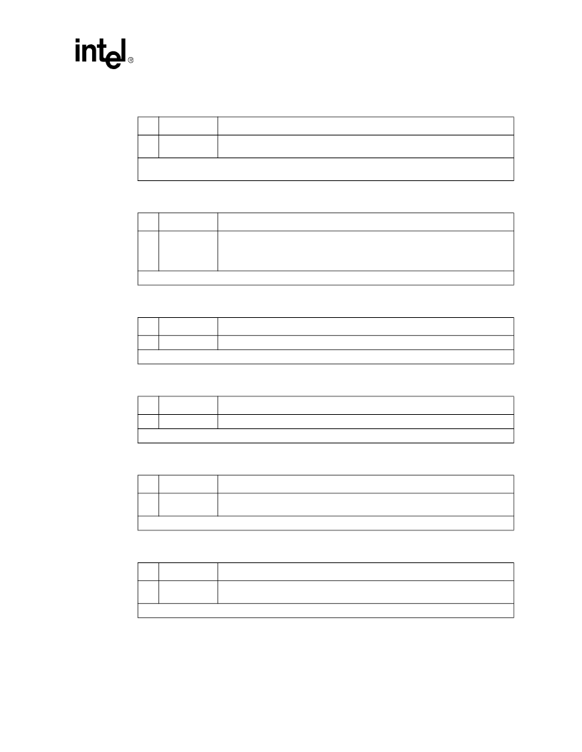
Table 12. LOS Status Monitor Register, LOS (04h)
Bit
1
Name
Function
7-0
LOS7-LOS0
Respective bit(s) are set to
“
1
”
every time the LOS processor detects a valid loss of
signal condition in transceivers 7-0.
1. On power up all register bits are set to
“
0
”
. Any change in the state causes an interrupt. All LOS interrupts
are cleared by a single read operation.
Table 13. DFM Status Monitor Register, DFM (05h)
Bit
Name
Function
1
7-0
DFM7-DFM0
Respective bit(s) are set to
“
1
”
every time the short circuit monitor detects a valid
secondary output driver short circuit condition in transceivers 7-0. Note: DFM is
available only in configurations with no transmit series resistors (T1 mode with
TVCC=3.3V).
1. On power-up all the register bits are set to
“
0
”
. All DFM interrupts are cleared by a single read operation.
Table 14. LOS Interrupt Enable Register, LIE (06h)
Bit
Name
Function
1
7-0
LIE7-LIE0
Transceiver 7-0 LOS interrupts are enabled by writing a
“
1
”
to the respective bit.
1. On power-up all the register bits are set to
“
0
”
and all interrupts are disabled.
Table 15. DFM Interrupt Enable Register, DIE (07h)
Bit
Name
Function
1
7-0
DIE7-DIE0
Transceiver 7-0 DFM interrupts are enabled by writing a
“
1
”
to the respective bit.
1. On power-up all the register bits are set to
“
0
”
and all interrupts are disabled.
Table 16. LOS Interrupt Status Register, LIS (08h)
Bit
Name
Function
1
7-0
LIS7-LIS0
These bits are set to
“
1
”
every time a LOS status change has occurred since the last
cleared interrupt in transceivers 7-0 respectively.
1. On power up all register bits are set to
“
0
”
.
Table 17. DFM Interrupt Status Register, DIS (09h)
Bit
Name
Function
1
7-0
DIS7-DIS0
These bits are set to
“
1
”
every time a DFM status change has occurred since the last
cleared interrupt in transceivers 7-0 respectively.
1. On power up all register bits are set to
“
0
”
.
相關(guān)PDF資料 |
PDF描述 |
|---|---|
| LXT400JE | Hermetically Sealed, 3.3V, High Speed, High CMR, Logic Gate Optocoupler |
| LXT6155LE | Telecomm/Datacomm |
| LXT6251A | ATM/SONET MAPPER|CMOS|QFP|208PIN|PLASTIC |
| LXT903PC | LAN Transceiver |
| LXT905LC | Laser Mouse VCSEL Assembly Clip |
相關(guān)代理商/技術(shù)參數(shù) |
參數(shù)描述 |
|---|---|
| LXT400 | 制造商:LVL1 制造商全稱:LVL1 功能描述:All Rate Extended Range Switched 56/DDS Transceiver |
| LXT400JE | 制造商:未知廠家 制造商全稱:未知廠家 功能描述:Transceiver Circuit For Telecommunications |
| LXT441 | 制造商:LVL1 制造商全稱:LVL1 功能描述:Switched 56/DDS Integrated DSU/CSU |
| LXT6155 | 制造商:INTEL 制造商全稱:Intel Corporation 功能描述:155 Mbps SDH/SONET/ATM Transceiver |
| LXT6155LE | 制造商:未知廠家 制造商全稱:未知廠家 功能描述:Telecomm/Datacomm |
發(fā)布緊急采購,3分鐘左右您將得到回復(fù)。