- 您現(xiàn)在的位置:買賣IC網(wǎng) > PDF目錄369873 > LV8572AVX Real-Time Clock PDF資料下載
參數(shù)資料
| 型號(hào): | LV8572AVX |
| 英文描述: | Real-Time Clock |
| 中文描述: | 實(shí)時(shí)時(shí)鐘 |
| 文件頁(yè)數(shù): | 16/24頁(yè) |
| 文件大小: | 353K |
| 代理商: | LV8572AVX |
第1頁(yè)第2頁(yè)第3頁(yè)第4頁(yè)第5頁(yè)第6頁(yè)第7頁(yè)第8頁(yè)第9頁(yè)第10頁(yè)第11頁(yè)第12頁(yè)第13頁(yè)第14頁(yè)第15頁(yè)當(dāng)前第16頁(yè)第17頁(yè)第18頁(yè)第19頁(yè)第20頁(yè)第21頁(yè)第22頁(yè)第23頁(yè)第24頁(yè)

Functional Description
(Continued)
TABLE VII. Register/Counter/RAM
Addressing for LV8571A
A0-4
PS
RS
Description
(Note 1) (Note 2)
CONTROL REGISTERS
00
01
02
03
04
01
02
03
04
X
0
0
0
0
0
0
0
0
X
0
0
0
0
1
1
1
1
Main Status Register
Timer 0 Control Register
Timer 1 Control Register
Periodic Flag Register
Interrupt Routing Register
Real Time Mode Register
Output Mode Register
Interrupt Control Register 0
Interrupt Control Register 1
COUNTERS (CLOCK CALENDAR)
05
06
07
08
09
0
0
0
0
0
X
X
X
X
X
1/100, 1/10 Seconds (0–99)
Seconds
Minutes
Hours
Days of
Month
Months
Years
Julian Date (LSB)
Julian Date
Day of Week
(0–59)
(0–59)
(1–12, 0–23)
(1–28/29/30/31)
(1–12)
(0–99)
(1–99)
(0–3)
(1–7)
0A
0B
0C
0D
0E
0
0
0
0
0
X
X
X
X
X
TIMER DATA REGISTERS
0F
10
11
12
0
0
0
0
X
X
X
X
Timer 0 LSB
Timer 0 MSB
Timer 1 LSB
Timer 1 MSB
TIME COMPARE RAM
13
14
15
0
0
0
X
X
X
Sec Compare RAM
Min Compare RAM
Hours Compare
RAM
DOM Compare
RAM
Months Compare
RAM
DOW Compare RAM (1–7)
(0–59)
(0–59)
(1–12, 0–23)
16
0
X
(1–28/29/30/31)
17
0
X
(1–12)
18
0
X
TIME SAVE RAM
19
1A
1B
1C
1D
0
0
0
0
0
X
X
X
X
X
Seconds Time Save RAM
Minutes Time Save RAM
Hours Time Save RAM
Day of Month Time Save RAM
Months Time Save RAM
1E
1F
0
0
1
X
RAM
RAM/Test Mode Register
01–1F
1
X
2nd Page General Purpose RAM
1 PSDPage Select (Bit D7 of Main Status Register)
2 RSDRegister Select (Bit D6 of Main Status Register)
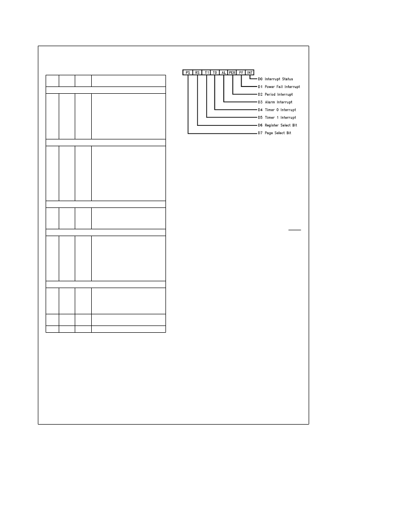
MAIN STATUS REGISTER
TL/F/11416–16
The Main Status Register is always located at address 0
regardless of the register block or the page selected.
D0:
This read only bit is a general interrupt status bit that is
taken directly from the interrupt pins. The bit is a one when
an interrupt is pending on either the INTR pin or the MFO
pin (when configured as an interrupt). This is unlike D3–D5
which can be set by an internal event but may not cause an
interrupt. This bit is reset when the interrupt status bits in the
Main Status Register are cleared.
D1–D5:
These five bits of the Main Status Register are the
main interrupt status bits. Any bit may be a one when any of
the interrupts are pending. Once an interrupt is asserted the
m
P will read this register to determine the cause. These
interrupt status bits are not reset when read. Except for D1,
to reset an interrupt a one is written back to the correspond-
ing bit that is being tested. D1 is reset whenever the PFAIL
pin
e
logic 1. This prevents loss of interrupt status when
reading the register in a polled mode. D1, D3–D5 are set
regardless of whether these interrupts are masked or not by
bits D6 and D7 of Interrupt Control Registers 0 and 1.
D6 and D7:
These bits are Read/Write bits that control
which register block or RAM page is to be selected. Bit D6
controls the register block to be accessed (see memory
map). The memory map of the clock is further divided into
two memory pages. One page is the registers, clock and
timers, and the second page contains 31 bytes of general
purpose RAM. The page selection is determined by bit D7.
16
相關(guān)PDF資料 |
PDF描述 |
|---|---|
| LV8800C | Optoelectronic |
| LVA12D | Analog IC |
| LVA12S | Analog IC |
| LVA15D | Analog IC |
| LVA15S | Analog IC |
相關(guān)代理商/技術(shù)參數(shù) |
參數(shù)描述 |
|---|---|
| LV8573A | 制造商:NSC 制造商全稱:National Semiconductor 功能描述:LV8573A Low Voltage Real Time Clock (RTC) |
| LV8573AM | 制造商:NSC 制造商全稱:National Semiconductor 功能描述:LV8573A Low Voltage Real Time Clock (RTC) |
| LV8573AN | 制造商:NSC 制造商全稱:National Semiconductor 功能描述:LV8573A Low Voltage Real Time Clock (RTC) |
| LV8573AV | 制造商:NSC 制造商全稱:National Semiconductor 功能描述:LV8573A Low Voltage Real Time Clock (RTC) |
| LV8573M | 制造商:NSC 制造商全稱:National Semiconductor 功能描述:LV8573A Low Voltage Real Time Clock (RTC) |
發(fā)布緊急采購(gòu),3分鐘左右您將得到回復(fù)。