- 您現(xiàn)在的位置:買賣IC網(wǎng) > PDF目錄383236 > L6256 (意法半導體) 12V COMBO PDF資料下載
參數(shù)資料
| 型號: | L6256 |
| 廠商: | 意法半導體 |
| 英文描述: | 12V COMBO |
| 中文描述: | 12V的組合 |
| 文件頁數(shù): | 15/28頁 |
| 文件大小: | 258K |
| 代理商: | L6256 |
第1頁第2頁第3頁第4頁第5頁第6頁第7頁第8頁第9頁第10頁第11頁第12頁第13頁第14頁當前第15頁第16頁第17頁第18頁第19頁第20頁第21頁第22頁第23頁第24頁第25頁第26頁第27頁第28頁
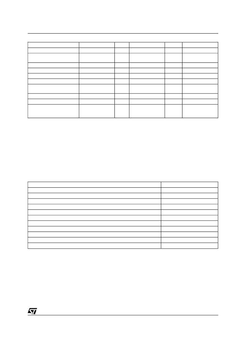
VCM Control Register
Bit Function
VCM DAC attenuation
switches - 3 bits (5)d
1.5:1
2:1
4:1
Thermal Limit
Register Park
Address: 0001
Init State
Mnemonic
Bit #
R/W
Read 1 indicates:
ATT0
ATT1
ATT2
TH_LIM
RPARK
0
1
2
3
4
xxx
xxx
xxx
0
On
W
W
W
N/A
N/A
N/A
Read
R/W
Th Limit
Park Delay is
Occuring (1)
Driver Saturated (2)
Tristated (3)
Current
Outside
Window (4)
Saturate Seek
VCM Tristate
VCM loopback (read)
SAT_SK
VCM_3S
VCM_LP
5
6
7
0
R/W
W
Read
xxx
xxx
Done Disable (write) (6)
DONE_DIS
7
Write
(1) Register park will not cause a brake to occur. The register park bit will also go low during a register brake, indicating to the firmware that
the brake sequence has been initiated.
(2) Saturated seek bit, when 1, will cause the VCM drivers to saturate, with the polarity of the sign bit in the VCM DAC register. A read of this
bit indicates that the commanded current differs from the actual current (output of the saturation comparator). NOTE: this is not just an
echo of the state of the written bit, but actually represents the true status of the VCM current loop.
(3) This bit tristates but leaves internal circuitry active for external test (ST), or is unused (Unitrode). The DONE_DIS bit has been moved
(see note 4).
(4) VCM loopback is optional. Use the saturated seek bit for test purposes. The DONE_DIS bit is used to end the park timer cycle, which
may be necessary if the chip is ever put into run mode at low speed.
(5) Exact attenuation ratios may vary slightly between manufacturers. See data sheets. Attenuators are now gated by ATT_EN, which is lo-
cated in S2 in the address space of the VCM register. IfATT_EN is high, the attenuation is set by the value in this register. If ATT_EN is
low, full gain (no attenuation) is selected. This allows rapid switching between low and high gain with the same write packet as that used
to write to the DAC.
(6) DONE_DIS MUST be cleared when entering run mode, or the park timer will stay off. This bit should never be used except during error
recovery.
Commutation Preload Register (CPR-Write only)
Bit Function
Spindle ABC low enb (3 bits)
A low enb
B low enb
C low enb
Spindle ABC high enb (3 bits)
A high enb
B high enb
C high enb
Spare
Spare
Address: 0011
Bit Address
initial state: XXX (2)
Bit 0
Bit 1
Bit 2
initial state: XXX (2)
Bit 3
Bit 4
Bit 5
Bit 6
Bit 7
NOTES:
- All bits become valid only on a rising SP_CLK edge, except CHB_ENB.
- Spindle high bits override low bits. Transition from low to high and vice versa are interlocked against simultaneous enables or momentary
shootthrough.
- An all 1’s pattern in this register, bits 0 through 5, causes the internal Commutation Counter to begin operation on the next SPIN_CLK input
edge. Any other pattern causes the spindle Commutation Counter to reset (BC\ state).
(1) CHB_ENB, when high (the POR and default condition), allows the back EMF chop blanking comparator to disable spindle PWM off peri-
ods during the A phase negative crossing (see back EMF detection section). Initial state varies between vendors.
(2) the 6 bits which determine the spindle driver must be set to all 1’s before entering run mode or the CCTR will not run.
L6256
15/28
相關(guān)PDF資料 |
PDF描述 |
|---|---|
| L6258E | PWM CONTROLLED - HIGH CURRENT DMOS UNIVERSAL MOTOR DRIVER |
| L6258EX | PWM CONTROLLED - HIGH CURRENT DMOS UNIVERSAL MOTOR DRIVER |
| L6260 | 4.5 - 5.5V DISK DRIVER SPINDLE & VCM, POWER & CONTROL COMBO’S |
| L6268 | 12V DISK DRIVE SPINDLE & VCM, POWER & CONTROL “COMBO” |
| L6269 | 12V DISK DRIVE SPINDLE & VCM, POWER & CONTROL “COMBO” |
相關(guān)代理商/技術(shù)參數(shù) |
參數(shù)描述 |
|---|---|
| L6258 | 制造商:STMICROELECTRONICS 制造商全稱:STMicroelectronics 功能描述:PWM controlled high current DMOS universal motor driver |
| L6258_07 | 制造商:STMICROELECTRONICS 制造商全稱:STMicroelectronics 功能描述:PWM controlled high current DMOS universal motor driver |
| L6258A | 制造商:未知廠家 制造商全稱:未知廠家 功能描述:Stepper Motor Controller/Driver |
| L6258E | 功能描述:馬達/運動/點火控制器和驅(qū)動器 Dual Full Bridge RoHS:否 制造商:STMicroelectronics 產(chǎn)品:Stepper Motor Controllers / Drivers 類型:2 Phase Stepper Motor Driver 工作電源電壓:8 V to 45 V 電源電流:0.5 mA 工作溫度:- 25 C to + 125 C 安裝風格:SMD/SMT 封裝 / 箱體:HTSSOP-28 封裝:Tube |
| L6258E_07 | 制造商:STMICROELECTRONICS 制造商全稱:STMicroelectronics 功能描述:PWM controlled high current DMOS universal motor driver |
發(fā)布緊急采購,3分鐘左右您將得到回復。