- 您現(xiàn)在的位置:買賣IC網(wǎng) > PDF目錄377488 > IDT88P8344BHGI (INTEGRATED DEVICE TECHNOLOGY INC) SPI EXCHANGE 4 x SPI-3 TO SPI-4 Issue 1.0 PDF資料下載
參數(shù)資料
| 型號: | IDT88P8344BHGI |
| 廠商: | INTEGRATED DEVICE TECHNOLOGY INC |
| 元件分類: | 微控制器/微處理器 |
| 英文描述: | SPI EXCHANGE 4 x SPI-3 TO SPI-4 Issue 1.0 |
| 中文描述: | SPECIALTY MICROPROCESSOR CIRCUIT, PBGA820 |
| 封裝: | GREEN, PLASTIC, BGA-820 |
| 文件頁數(shù): | 21/98頁 |
| 文件大小: | 601K |
| 代理商: | IDT88P8344BHGI |
第1頁第2頁第3頁第4頁第5頁第6頁第7頁第8頁第9頁第10頁第11頁第12頁第13頁第14頁第15頁第16頁第17頁第18頁第19頁第20頁當(dāng)前第21頁第22頁第23頁第24頁第25頁第26頁第27頁第28頁第29頁第30頁第31頁第32頁第33頁第34頁第35頁第36頁第37頁第38頁第39頁第40頁第41頁第42頁第43頁第44頁第45頁第46頁第47頁第48頁第49頁第50頁第51頁第52頁第53頁第54頁第55頁第56頁第57頁第58頁第59頁第60頁第61頁第62頁第63頁第64頁第65頁第66頁第67頁第68頁第69頁第70頁第71頁第72頁第73頁第74頁第75頁第76頁第77頁第78頁第79頁第80頁第81頁第82頁第83頁第84頁第85頁第86頁第87頁第88頁第89頁第90頁第91頁第92頁第93頁第94頁第95頁第96頁第97頁第98頁
21
IDT88P8344 SPI EXCHANGE 4 x SPI-3 TO SPI-4
INDUSTRIAL TEMPERATURE RANGE
APRIL 10, 2006
SPI-4 egress status channel
Status channel bit alignment
The bit alignment algorithmfor the status channel is the same as was described
for the data channel.
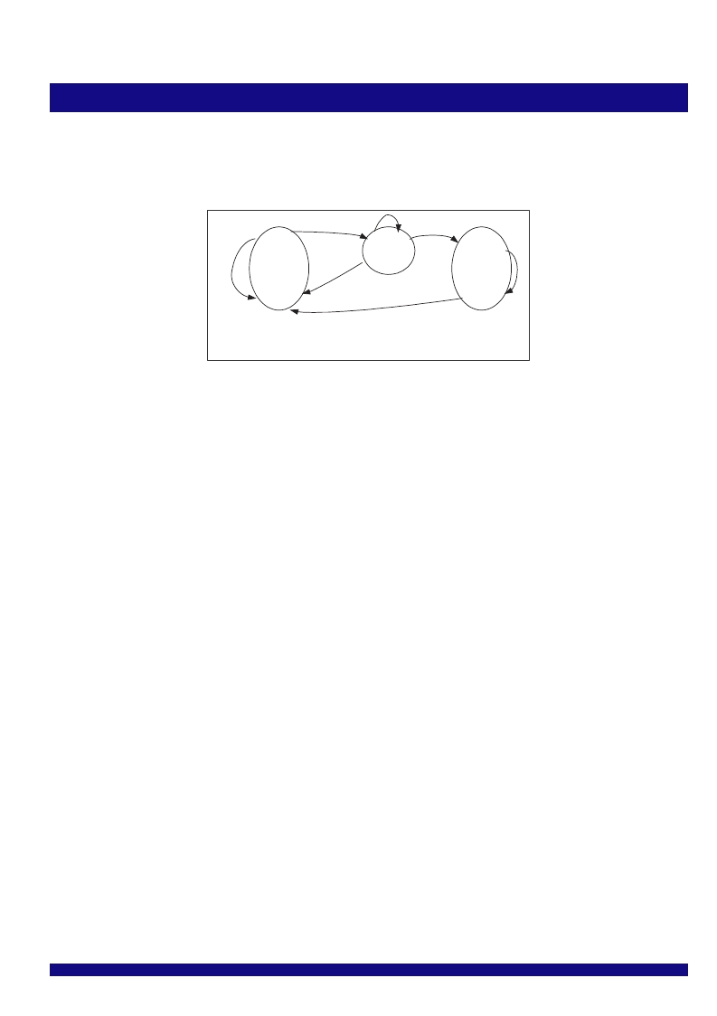
Validate
IN_SYNCH
A
B
A= a number of consecutive error free DIP-2s received
B= a number of consecutive DIP-2 errors, in training,
port disabled, or reset
HUNT
C
D
6370 drw30
Figure 9. SPI-4 egress status state diagram
The status channel frame module has 3 states: HUNT, VALIDATE and
IN_SYNCH.
In the HUNT state, the status channel frame module searches for status
frame, status clear and status freeze.
In the VALIDATE state, the status channel frame module checks DIP-2.
In the IN_SYNCH state, the status channel frame module checks DIP-2, and
updates status.
HUNT state
In the HUNT state, per Link status is fixed to satisfied.
In HUNT state, the PFP searches frame continuously. It transitions to the
VALIDATE state if a single valid frame is found accompanied by a single valid
training pattern. A frame is considered to be found if : 1) only one frame word
is at the beginning of a frame, 2) the calendar selection word, if enabled, is
matched, and 3) the DIP-2 calculation matched the received DIP-2.
VALIDATE state
In the validate state, based on the frame found while in the HUNT state,
the DIP-2 is checked.
If a single DIP-2 error is found, transition to the HUNT state.
After a number of consecutive DIP-2 calculations proves to be error free,
transition to the IN_SYNCH state. The number is defined by the E_INSYNC_THR
field in Table 104-SPI-4 egress configuration register_0 (Block_base 0x0700
+ Register_offset 0x00).
In the validate state, the training pattern is not checked.
IN_SYNCH state
In the IN_SYNCH state, training frame and status frame are checked.
DIP-2 is checked for status frame. Each msmatched DIP-2 will generate a
DIP-2 error event, each event will be captured and counted.
After a number of consecutive DIP-2 errors, transition to the HUNT state.
(Clear status in HUNT mode). The number is defined by the E_OUTSYNC_THR
field in Table 104-SPI-4 egress configuration register_0 (Block_base 0x0700
+ Register_offset 0x00).
The reception of twelve consecutive training patterns forces a transition to
HUNT mode. If less than twelve consecutive training patterns are received,
synch will not be lost, and status frame starts at the end of training.
Twelve consecutive 11’ patterns force a transition to the HUNT state.
Status updating occurs without waiting for the end of a status frame.
LVTTL or LVDS status channel option
The LVDS_STA pin selects the interface type. A logic high enables the LVDS
status interface. A logic low enables the LVTTL status interface.
Data channel
Data transfer and training
At any cycle, the contents on the interface can be one of the following:
Control word: Payload control word, or idle control word or training control
word.
Data word: Payload data word or training data word.
In the HUNT or the VALIDATE state, the training pattern is sent.
In the IN_SYNCH state, data fromis taken fromthe buffer segments and
egressed to the SPI-4 interface. The switch between data burst, IDLE, and
training must obey the following rules:
Send IDLE if no data to transmt
SOP must not occur less than 8 cycles apart.
periodic training after current transfer finished
Payload control word generation:
Bit 15, Control word type=1
Bit [14:13] EOPS per [see Glossary: SPI-4]. If an error tag is in the
descriptor, abort.
Bit [12] SOP refer to [see Glossary: SPI-4]
Eight Bit Address. Mapping table defined in Table 101, SPI-4 egress LID
to LP map (256 entries)
DIP-4 bit refer to [see Glossary]
Payload data word
Bit order refer to [see Glossary: SPI-4]
If only one byte is valid, 8 LSB (B7 to B0) is set to 0x00.
No status channel option
Once the NOSTAT bit is set, the status channel is ignored. Refer to Table 104,
SPI-4 egress configuration register_0 (register_offset 0x00).
Status in default value.
No DIP error check.
No status updating, the received status fixed to STARVING.
Data channel works same as in IN_SYNCH state.
Status Channel Frame synchronization
Status channel de-skew
The LVDS status channel deskew uses the same algorithmas the as the data
channel.
相關(guān)PDF資料 |
PDF描述 |
|---|---|
| IDTAMB0480 | ADVANCED MEMORY BUFFER FOR FULLY BUFFERED DIMM MODULES |
| IDTCSP2510DPGI | 3.3V PHASE-LOCK LOOP CLOCK DRIVER ZERO DELAY BUFFER |
| IDTCSP2510DPG | SENSOR OPTICAL SLOTTED 1.0MM |
| IDTCSP2510D | 3.3V PHASE-LOCK LOOP CLOCK DRIVER ZERO DELAY BUFFER |
| IDTCSPT857CNL | 2.5V - 2.6V PHASE LOCKED LOOP DIFFERENTIAL 1:10 SDRAM CLOCK DRIVER |
相關(guān)代理商/技術(shù)參數(shù) |
參數(shù)描述 |
|---|---|
| IDT88P8344BHI | 功能描述:IC SPI3-SPI4 EXCHANGE 820-PBGA RoHS:否 類別:集成電路 (IC) >> 專用 IC 系列:* 產(chǎn)品培訓(xùn)模塊:Lead (SnPb) Finish for COTS Obsolescence Mitigation Program 標(biāo)準包裝:1 系列:- 類型:調(diào)幀器 應(yīng)用:數(shù)據(jù)傳輸 安裝類型:表面貼裝 封裝/外殼:400-BBGA 供應(yīng)商設(shè)備封裝:400-PBGA(27x27) 包裝:散裝 |
| IDT89H10T4BG2ZBBC | 制造商:Integrated Device Technology Inc 功能描述:IC PCI SW 10LANE 4PORT 324BGA |
| IDT89H10T4BG2ZBBC8 | 制造商:Integrated Device Technology Inc 功能描述:IC PCI SW 10LANE 4PORT 324BGA |
| IDT89H10T4BG2ZBBCG | 功能描述:IC PCI SW 10LANE 4PORT 324BGA RoHS:是 類別:集成電路 (IC) >> 專用 IC 系列:PRECISE™ 產(chǎn)品培訓(xùn)模塊:Lead (SnPb) Finish for COTS Obsolescence Mitigation Program 標(biāo)準包裝:1 系列:- 類型:調(diào)幀器 應(yīng)用:數(shù)據(jù)傳輸 安裝類型:表面貼裝 封裝/外殼:400-BBGA 供應(yīng)商設(shè)備封裝:400-PBGA(27x27) 包裝:散裝 |
| IDT89H10T4BG2ZBBCG8 | 制造商:Integrated Device Technology Inc 功能描述:IC PCI SW 10LANE 4PORT 324BGA |
發(fā)布緊急采購,3分鐘左右您將得到回復(fù)。