- 您現(xiàn)在的位置:買賣IC網(wǎng) > PDF目錄377487 > IDT821068 (Integrated Device Technology, Inc.) OCTAL PROGRAMMABLE PCM CODEC PDF資料下載
參數(shù)資料
| 型號(hào): | IDT821068 |
| 廠商: | Integrated Device Technology, Inc. |
| 元件分類: | Codec |
| 英文描述: | OCTAL PROGRAMMABLE PCM CODEC |
| 中文描述: | 八路可編程PCM編解碼器 |
| 文件頁數(shù): | 8/45頁 |
| 文件大?。?/td> | 589K |
| 代理商: | IDT821068 |
第1頁第2頁第3頁第4頁第5頁第6頁第7頁當(dāng)前第8頁第9頁第10頁第11頁第12頁第13頁第14頁第15頁第16頁第17頁第18頁第19頁第20頁第21頁第22頁第23頁第24頁第25頁第26頁第27頁第28頁第29頁第30頁第31頁第32頁第33頁第34頁第35頁第36頁第37頁第38頁第39頁第40頁第41頁第42頁第43頁第44頁第45頁
INDUSTRIAL TEMPERATURE RANGE
IDT821068 OCTAL PROGRAMMABLE PCM CODEC
8
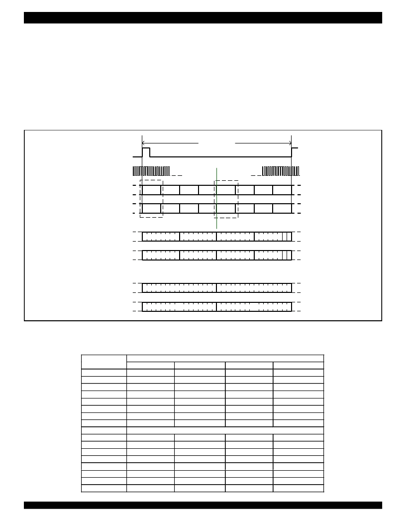
Linear GCI Structure
In GCI linear mode, one GCI frame consists of 8 GCI time slots,
each GCI time slot consists of four 8-bit bytes. Four of the 8 time slots
are used as Monitor Channel and C/I octet, they have a common data
structure:
- Two Don’t Care bytes.
- One monitor channel byte, which is used for reading/writing control
data/coefficients from/to the device for channel A and B.
- One C/I byte, which contains a 6 bit width C/I channel sub-byte
together with an MX bit and an MR bit. All real time signaling
information is carried on the C/I channel sub-byte. The MX (Monitor
Figure 5. Linear GCI Frame Structure When TS Is Low
TS0
TS1
TS2
TS3
TS4
TS5
TS6
TS7
TS0
TS1
TS2
TS3
TS4
TS5
TS6
TS7
Detail A
Don't Care
Don't Care
Monitor Channel
C/I Channel
M
R
M
X
Don't Care
Don't Care
Monitor Channel
C/I Channel
M
R
M
X
125
μ
s
FSC
DCL
DD
DU
DU
DD
Detail A
Detail B
DU
DD
Detail B
16-bit Linear Voice Data for Channel A
16-bit Linear Voice Data for Channel B
16-bit Linear Voice Data for Channel A
16-bit Linear Voice Data for Channel B
TS0-3 for Monitor and C/I
TS4-7 for Linear Voice
Data
TS = 0
IDT821068
Channels
1
2
3
4
5
6
7
8
Timeslot
Timeslot0
Timeslot0
Timeslot1
Timeslot1
Timeslot2
Timeslot2
Timeslot3
Timeslot3
Monitor and C/I
A
B
A
B
A
B
A
B
Timeslot
Timeslot4
Timeslot4
Timeslot5
Timeslot5
Timeslot6
Timeslot6
Timeslot7
Timeslot7
Voice Channel
A
B
A
B
A
B
A
B
TS = 1
1
2
3
4
5
6
7
8
Timeslot4
Timeslot4
Timeslot5
Timeslot5
Timeslot6
Timeslot6
Timeslot7
Timeslot7
A
B
A
B
A
B
A
B
Timeslot0
Timeslot0
Timeslot1
Timeslot1
Timeslot2
Timeslot2
Timeslot3
Timeslot3
A
B
A
B
A
B
A
B
Transmit) bit and MR (Monitor Receive) bits are used for handshaking
functions for channel A and B. Both MX and MR bits are active low.
Other four GCI time slots are used for linear voice data (16-bit 2’s
complement). Each time slot consists of two 16-bit linear voice data
bytes: one byte contains the linear voice data for channel A, the other
byte contains the linear voice data for channel B.
The GCI time slot assignment is determined by the TS pin. When
TS is low, the linear GCI Frame Structure is shown in Figure 5.
In linear operation, total eight GCI time slots are required to access
the eight channels of IDT821068. See Table 2 for detailed information
about time slot assignment for linear mode.
Table 2 - Time Slot Selection for linear GCI
相關(guān)PDF資料 |
PDF描述 |
|---|---|
| IDT821068PX | OCTAL PROGRAMMABLE PCM CODEC |
| IDT821621 | LONG HAUL SLIC |
| IDT821621J | LONG HAUL SLIC |
| IDT82P2281 | Single T1/E1/J1 Long Haul Short Haul Transceiver |
| IDT82P2281PN | Single T1/E1/J1 Long Haul Short Haul Transceiver |
相關(guān)代理商/技術(shù)參數(shù) |
參數(shù)描述 |
|---|---|
| IDT821068PX | 制造商:IDT 制造商全稱:Integrated Device Technology 功能描述:OCTAL PROGRAMMABLE PCM CODEC |
| IDT821621 | 制造商:IDT 制造商全稱:Integrated Device Technology 功能描述:LONG HAUL SLIC |
| IDT821621J | 制造商:IDT 制造商全稱:Integrated Device Technology 功能描述:LONG HAUL SLIC |
| IDT8217LP35P | 制造商:Integrated Device Technology Inc 功能描述: |
| IDT82ALVCH16823PA | 制造商:IDT 制造商全稱:Integrated Device Technology 功能描述:3.3V CMOS 18-BIT BUS-INTERFACE FLIPFLOP WITH 3-STATE OUTPUTS AND BUS-HOLD |
發(fā)布緊急采購,3分鐘左右您將得到回復(fù)。