- 您現(xiàn)在的位置:買賣IC網(wǎng) > PDF目錄377487 > IDT821068 (Integrated Device Technology, Inc.) OCTAL PROGRAMMABLE PCM CODEC PDF資料下載
參數(shù)資料
| 型號(hào): | IDT821068 |
| 廠商: | Integrated Device Technology, Inc. |
| 元件分類: | Codec |
| 英文描述: | OCTAL PROGRAMMABLE PCM CODEC |
| 中文描述: | 八路可編程PCM編解碼器 |
| 文件頁數(shù): | 27/45頁 |
| 文件大小: | 589K |
| 代理商: | IDT821068 |
第1頁第2頁第3頁第4頁第5頁第6頁第7頁第8頁第9頁第10頁第11頁第12頁第13頁第14頁第15頁第16頁第17頁第18頁第19頁第20頁第21頁第22頁第23頁第24頁第25頁第26頁當(dāng)前第27頁第28頁第29頁第30頁第31頁第32頁第33頁第34頁第35頁第36頁第37頁第38頁第39頁第40頁第41頁第42頁第43頁第44頁第45頁
INDUSTRIAL TEMPERATURE RANGE
IDT821068 OCTAL PROGRAMMABLE PCM CODEC
27
SB2C[3] = 0: SB2 pin on Channel 4 is configured as input (default);
SB2C[3] = 1: SB2 pin on Channel 4 is configured as output;
SB2C[4] = 0: SB2 pin on Channel 5 is configured as input (default);
SB2C[4] = 1: SB2 pin on Channel 5 is configured as output;
SB2C[5] = 0: SB2 pin on Channel 6 is configured as input (default);
SB2C[5] = 1: SB2 pin on Channel 6 is configured as output;
SB2C[6] = 0: SB2 pin on Channel 7 is configured as input (default);
SB2C[6] = 1: SB2 pin on Channel 7 is configured as output;
SB2C[7] = 0: SB2 pin on Channel 8 is configured as input (default);
SB2C[7] = 1: SB2 pin on Channel 8 is configured as output;
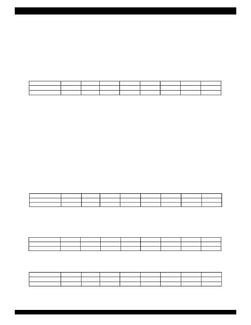
15. SLIC Ring Trip Setting (2EH/AEH), Read/Write
Output Selection bits OS[2:0] determine which output pin will be selected as the ring control signal source.
OS = 000 - 010: not defined;
OS = 011: SB1 is selected (when it is configured as an output);
OS = 100: SB2 is selected (when it is configured as an output);
OS = 101: SO1 is selected;
OS = 110: SO2 is selected;
OS = 111: SO3 is selected.
Ring Trip Enable bit RTE enables or disables the ring trip function block:
RTE = 0: the ring trip function block is disabled (default);
RTE = 1: the ring trip function block is enabled.
Input Selection bit IS determines which input will be selected as the off-hook indication signal source.
IS = 0: SI1 is selected (default);
Input Polarity Indicator bit IPI indicates the valid polarity of input.
IPI = 0: active low (default); IPI = 1: active high.
Output Polarity Indicator bit OPI indicates the valid polarity of output.
OPI = 0: the selected output pin changes from high to low to activate the ring (default);
OPI = 1: the selected output pin changes from low to hight to activate the ring.
IS = 1: SI2 is selected.
16. Level Meter Result Low Register (30H), Read Only
This register contains the lower 8 bits of Level Meter output with the default value of ‘0000-0000’, LVLL[0] is the active high data_ready bit. To
read the level meter result, users should read the low register which contains LVLL[7:0] data first, then read the high register which contains
LVLH[7:0] data. Once the high register is read, the LVLL[0] bit is cleared immediately.
17. Level Meter Result High Register (31H), Read Only
This register contains the higher 8 bits of Level Metering output with the default value of 0(d).
18. Level Meter Counter (32H/B2H), Read/Write
Level Meter Counter register is used to configure the number of time cycles for sampling PCM data.
CN = 0 (d): the linear or compressed PCM data is output to LMRH and LMRL directly (default);
CN = N: PCM data is sampled for N * 125
μ
s (N from 1 to 255).
b7
R
/W
OPI
b6
0
R
b5
1
IPI
b4
0
IS
b3
1
RTE
b2
1
b1
1
b0
0
Command
I/O data
OS[2]
OS[1]
OS[0]
b7
0
b6
0
b5
1
b4
1
b3
0
b2
0
b1
0
b0
0
Command
I/O data
LMRL[7]
LMRL[6]
LMRL[5]
LMRL[4]
LMRL[3]
LMRL[2]
LMRL[1]
DRLV
b7
0
b6
0
b5
1
b4
1
b3
0
b2
0
b1
0
b0
1
Command
I/O data
LMRH[7]
LMRH[6]
LMRH[5]
LMRH[4]
LMRH[3]
LMRH[2]
LMRH[1]
LMRH[0]
b7
R
/W
CN[7]
b6
0
b5
1
b4
1
b3
0
b2
0
b1
1
b0
0
Command
I/O data
CN[6]
CN[5]
CN[4]
CN[3]
CN[2]
CN[1]
CN[0]
相關(guān)PDF資料 |
PDF描述 |
|---|---|
| IDT821068PX | OCTAL PROGRAMMABLE PCM CODEC |
| IDT821621 | LONG HAUL SLIC |
| IDT821621J | LONG HAUL SLIC |
| IDT82P2281 | Single T1/E1/J1 Long Haul Short Haul Transceiver |
| IDT82P2281PN | Single T1/E1/J1 Long Haul Short Haul Transceiver |
相關(guān)代理商/技術(shù)參數(shù) |
參數(shù)描述 |
|---|---|
| IDT821068PX | 制造商:IDT 制造商全稱:Integrated Device Technology 功能描述:OCTAL PROGRAMMABLE PCM CODEC |
| IDT821621 | 制造商:IDT 制造商全稱:Integrated Device Technology 功能描述:LONG HAUL SLIC |
| IDT821621J | 制造商:IDT 制造商全稱:Integrated Device Technology 功能描述:LONG HAUL SLIC |
| IDT8217LP35P | 制造商:Integrated Device Technology Inc 功能描述: |
| IDT82ALVCH16823PA | 制造商:IDT 制造商全稱:Integrated Device Technology 功能描述:3.3V CMOS 18-BIT BUS-INTERFACE FLIPFLOP WITH 3-STATE OUTPUTS AND BUS-HOLD |
發(fā)布緊急采購,3分鐘左右您將得到回復(fù)。