- 您現(xiàn)在的位置:買賣IC網(wǎng) > PDF目錄377487 > IDT821068 (Integrated Device Technology, Inc.) OCTAL PROGRAMMABLE PCM CODEC PDF資料下載
參數(shù)資料
| 型號: | IDT821068 |
| 廠商: | Integrated Device Technology, Inc. |
| 元件分類: | Codec |
| 英文描述: | OCTAL PROGRAMMABLE PCM CODEC |
| 中文描述: | 八路可編程PCM編解碼器 |
| 文件頁數(shù): | 19/45頁 |
| 文件大?。?/td> | 589K |
| 代理商: | IDT821068 |
第1頁第2頁第3頁第4頁第5頁第6頁第7頁第8頁第9頁第10頁第11頁第12頁第13頁第14頁第15頁第16頁第17頁第18頁當(dāng)前第19頁第20頁第21頁第22頁第23頁第24頁第25頁第26頁第27頁第28頁第29頁第30頁第31頁第32頁第33頁第34頁第35頁第36頁第37頁第38頁第39頁第40頁第41頁第42頁第43頁第44頁第45頁
INDUSTRIAL TEMPERATURE RANGE
IDT821068 OCTAL PROGRAMMABLE PCM CODEC
19
b7 b6 b5 b4 b3 b2 b1 b0
OPERATING THE IDT821068
PROGRAMMING DESCRIPTION
The IDT821068 can be programmed very flexibly via the serial
control interface (MPI mode) or GCI monitor channel (GCI mode). In
both MPI mode and GCI mode, the programming is realized by
writing commands to registers or RAMs in the chip. In MPI mode, the
command data is transmitted/received via CI/CO pin; while in GCI
mode, command data is sent/received via DD/DU pin.
BROADCAST MODE FOR MPI PROGRAMMING
A broadcast mode is provided in MPI write-operation (not allowed in
a read-operation). Each channel has its own enable bit (CE[0] to CE[7]
in Global Register 6) to allow individual channel programming. If more
than one Channel Enable bit is high (enable) or if all Channel Enable
bits are high, all channels enabled will receive the programming
information written; therefore, a Broadcast mode can be implemented
by simply enable all the channels in the device to receive the
programming information. The Broadcast mode is very useful in
initializing IDT821068 such as coefficient setting in a large system.
IDENTIFICATION CODE FOR MPI MODE
In MPI mode, IDT821068 provides an Identification Code to
distinguish itself from other device of the system. When being read,
IDT821068 outputs an Identification Code of 81H before data bytes,
which indicate that the following data is from IDT821068.
PROGRAM START BYTE FOR GCI MODE
The IDT821068 uses the monitor channel for the exchange of
status or mode information with high level processors. The messages
transmitted in the monitor channel have different data structures. For a
complete command operation, the first byte of monitor channel data
indicates the address of the device either sending or receiving the
data. All monitor channel messages to/from IDT821068 begin with the
following Program Start (PS) byte:
Because one monitor channel is shared by two voice data channels
to transmit maintenance information, so an
A
/B bit is used in the PS
byte to identify the two channels. For easy description, we name them
as Channel A and Channel B. Herein,
A
/B = 0: means that Channel A is the source (upstream) or
destination (downstream) -81H;
A
/B = 1: means that Channel B is the source (upstream) or
destination (downstream) -91H.
The Program Start byte is followed by a command (global/local
register command or RAM command) byte. For Global Command,
the
A
/B bit in the PS byte can be ignored. If the command byte
specifies a write, then from 1 to 16 additional data bytes may follow (1-
4 for registers, 1-16 for RAM). If the command byte specifies a read,
additional data bytes may follow. IDT821068 responds to the read
command by sending up to 16 data bytes upstream containing the
information requested by the upstream controller. Each byte on
monitor channel must be transferred at least twice and in two
consecutive frames.
IDENTIFICATION COMMAND FOR GCI MODE
In order to distinguish different devices unambiguously by software,
a two byte identification command is defined for analog lines GCI
devices (8000H):
1
0
0
0
0
0
0
0
0
0
0
0
0
0
0
0
1
0
0
0
0
0
0
0
1
0
0
0
0
0
1
0
Each device will then respond with its specific identification code. For
IDT821068, this two byte identification code is (8082H):
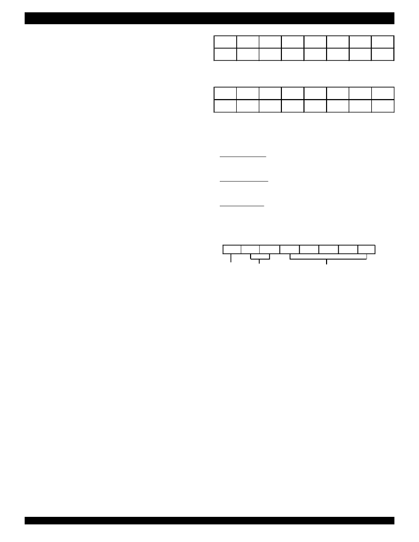
COMMAND TYPE AND FORMAT
IDT821068 provides three types of register/RAM commands for
both MPI and GCI operation, they are:
Local Command, which is used to configure each channel by
reading/writing the Local Registers, there are 14 Local Registers per
channel available;
Global Command, which is used to configure all 8 channels by
reading/writing the Global Registers, there are totally 26 Global
Registers shared by the 8 channels;
RAM Command, which is used to read/write the Coe-RAM and
FSK-RAM, there are 40 words (divided into 5 blocks) with 14 bits per
word Coe-RAM for each channel, and 32 words (divided into 4 blocks)
with 16 bits per word FSK-RAM shared by the 8 channels.
The format of the commands is as the following:
R
/W CT Address
R
/W: Read/Write Command bit.
b7 = 0: Read Command
b7 = 1: Write Command
CT: Command Type
b6 b5 = 00: LC - Local Command
b6 b5 = 01: GC - Global Command
b6 b5 = 10: Not Allowed
b6 b5 = 11: RC - RAM Command
Address: Specify which register or which block of RAM will be read
or written.
For both Local Command and Global Command, b[4:0] are used to
address the Local Registers or Global Registers.
For RAM Command, b4 is used to distinguish the Coe-RAM and the
FSK RAM:
b4 = 0: The RAM Command is for Coe-RAM
b4 = 1: The RAM Command is for FSK-RAM
When the RAM Command is for Coe-RAM, b[3:0] are used to
address the blocks in the Coe-RAM. When the RAM Command is for
FSK-RAM, b3 is always 0’ and b[2:0] are used to address the blocks
in the FSK-RAM.
ADDRESSING LOCAL REGISTER
In MPI mode, when using Local Command, the Channel Enable
Command (Global Command 6) must be used first to specify which
channel will be addressed, then the Local Command follows. If Global
Command 6 enable more than one channel, then all the channels
enabled will be addressed by one Local Command at one time.
相關(guān)PDF資料 |
PDF描述 |
|---|---|
| IDT821068PX | OCTAL PROGRAMMABLE PCM CODEC |
| IDT821621 | LONG HAUL SLIC |
| IDT821621J | LONG HAUL SLIC |
| IDT82P2281 | Single T1/E1/J1 Long Haul Short Haul Transceiver |
| IDT82P2281PN | Single T1/E1/J1 Long Haul Short Haul Transceiver |
相關(guān)代理商/技術(shù)參數(shù) |
參數(shù)描述 |
|---|---|
| IDT821068PX | 制造商:IDT 制造商全稱:Integrated Device Technology 功能描述:OCTAL PROGRAMMABLE PCM CODEC |
| IDT821621 | 制造商:IDT 制造商全稱:Integrated Device Technology 功能描述:LONG HAUL SLIC |
| IDT821621J | 制造商:IDT 制造商全稱:Integrated Device Technology 功能描述:LONG HAUL SLIC |
| IDT8217LP35P | 制造商:Integrated Device Technology Inc 功能描述: |
| IDT82ALVCH16823PA | 制造商:IDT 制造商全稱:Integrated Device Technology 功能描述:3.3V CMOS 18-BIT BUS-INTERFACE FLIPFLOP WITH 3-STATE OUTPUTS AND BUS-HOLD |
發(fā)布緊急采購,3分鐘左右您將得到回復(fù)。