- 您現(xiàn)在的位置:買賣IC網(wǎng) > PDF目錄377487 > IDT821064 (Integrated Device Technology, Inc.) QUAD PROGRAMMABLE PCM CODEC WITH GCI INTERFACE PDF資料下載
參數(shù)資料
| 型號: | IDT821064 |
| 廠商: | Integrated Device Technology, Inc. |
| 元件分類: | Codec |
| 英文描述: | QUAD PROGRAMMABLE PCM CODEC WITH GCI INTERFACE |
| 中文描述: | 四可編程PCM編解碼器GCI界面 |
| 文件頁數(shù): | 24/33頁 |
| 文件大小: | 510K |
| 代理商: | IDT821064 |
第1頁第2頁第3頁第4頁第5頁第6頁第7頁第8頁第9頁第10頁第11頁第12頁第13頁第14頁第15頁第16頁第17頁第18頁第19頁第20頁第21頁第22頁第23頁當前第24頁第25頁第26頁第27頁第28頁第29頁第30頁第31頁第32頁第33頁

24
INDUSTRIAL TEMPERATURE RANGE
IDT821064 QUAD PROGRAMMABLE PCM CODEC WITH GCI INTERFACE
LOCAL COMMANDS:
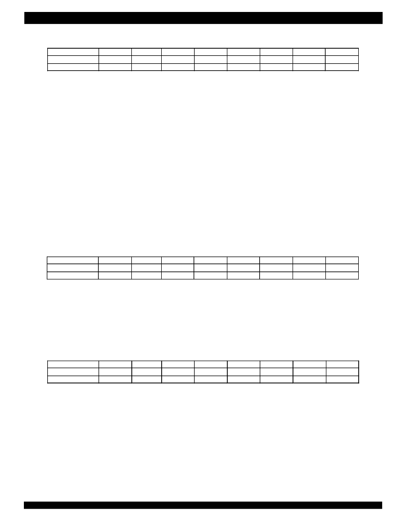
1. Coefficient Select (00H/80H), Read/Write
Coefficient Select bits (CS[7:0]) are used to control digital filters and function blocks on corresponding channel such as Impedance Matching
Filter, Echo Cancellation Filter, High-Pass Filter, Gain for Impedance Scaling, Gain in Transmit/Receive Path and Frequency Response Correction
in Transmit/Receive Path. See Figure 6 for details. It should be noted that Impedance Matching Filter and Gain for Impedance Scaling are working
together to adjust impedance. That is to say, CS [0] and CS[2] should be set to the same value to ensure the correct operation.
CS [7] = 0: Gain in Receive Path coefficient is set to default value (default);
CS [7] = 1: Gain in Receive Path coefficient is set by GRX RAM.
CS [6] = 0: Frequency Response Correction in Receive Path coefficient is set to default value (default);
CS [6] = 1: Frequency Response Correction in Receive Path coefficient is set by FRR RAM;
CS [5] = 0: Gain in Transmit Path coefficient is set to default value (default);
CS [5] = 1: Gain in Transmit Path coefficient is set by GTX RAM;
CS [4] = 0: Frequency Response Correction in Transmit Path coefficient is set to default value (default);
CS [4] = 1: Frequency Response Correction in Transmit Path coefficient is set by FRX RAM;
CS [3] = 0: High-Pass Filter is bypassed/disabled;
CS [3] = 1: High-Pass Filter is enabled (default);
CS [2] = 0: Gain for Impedance Scaling coefficient is set to default value (default);
CS [2] = 1: Gain for Impedance Scaling coefficient is set by GIS RAM;
CS [1] = 0: Echo Cancellation Filter coefficient is set to default value (default);
CS [1] = 1: Echo Cancellation Filter coefficient is set by ECF RAM;
CS [0] = 0: Impedance Matching Filter coefficient is set to default value (default);
CS [0] = 1: Impedance Matching Filter coefficient is set by IMF RAM;
2. Loop Status Control (01H/81H), Read/Write
Loop Status Control Bits (LPC[2:0]) determine the loopback status on corresponding channel. Refer to Figure 6 for detailed information.
LPC[2] = 0: Digital Loopback via Time slots is disabled on the corresponding channel (default);
LPC[2] = 1: Digital Loopback via Time slots is enabled on the corresponding channel.
LPC[1] = 0: Analog Loopback via Onebit is disabled on the corresponding channel (default);
LPC[1] = 1: Analog Loopback via Onebit is enabled on the corresponding channel;
LPC[0] = 0: Digital Loopback via Onebit is disabled on the corresponding channel (default);
LPC[0] = 1: Digital loopback via Onebit is enabled on the corresponding channel;
3. DSH Debounce and GK Debounce (02H/82H), Read/Write
DSH Debounce bits DSH[3:0] set the debounce time of SI1 input from SLIC for corresponding channel.
DSH[3:0] = 0000: 0 ms (default);
DSH[3:0] = 0001: 2 ms;
DSH[3:0] = 0010: 4 ms;
DSH[3:0] = 0011: 6 ms;
DSH[3:0] = 0100: 8 ms;
DSH[3:0] = 0101: 10 ms;
DSH[3:0] = 0110: 12 ms;
DSH[3:0] = 0111: 14 ms;
DSH[3:0] = 1000: 16 ms;
DSH[3:0] = 1001: 18 ms;
DSH[3:0] = 1010: 20 ms;
b7
R
/W
CS[7]
b6
0
b5
0
b4
0
b3
0
b2
0
b1
0
b0
0
Command
I/O data
CS[6]
CS[5]
CS[4]
CS[3]
CS[2]
CS[1]
CS[0]
b7
R
/W
R
b6
0
R
b5
0
R
b4
0
R
b3
0
R
b2
0
b1
0
b0
1
Command
I/O data
LPC[2]
LPC[1]
LPC[0]
b7
R
/W
GK[3]
b6
0
b5
0
b4
0
b3
0
b2
0
b1
1
b0
0
Command
I/O data
GK[2]
GK[1]
GK[0]
DSH[3]
DSH[2]
DSH[1]
DSH[0]
相關(guān)PDF資料 |
PDF描述 |
|---|---|
| IDT821064PQF | QUAD PROGRAMMABLE PCM CODEC WITH GCI INTERFACE |
| IDT821068 | OCTAL PROGRAMMABLE PCM CODEC |
| IDT821068PX | OCTAL PROGRAMMABLE PCM CODEC |
| IDT821621 | LONG HAUL SLIC |
| IDT821621J | LONG HAUL SLIC |
相關(guān)代理商/技術(shù)參數(shù) |
參數(shù)描述 |
|---|---|
| IDT821064PQF | 制造商:IDT 制造商全稱:Integrated Device Technology 功能描述:QUAD PROGRAMMABLE PCM CODEC WITH GCI INTERFACE |
| IDT821068 | 制造商:IDT 制造商全稱:Integrated Device Technology 功能描述:OCTAL PROGRAMMABLE PCM CODEC |
| IDT821068PX | 制造商:IDT 制造商全稱:Integrated Device Technology 功能描述:OCTAL PROGRAMMABLE PCM CODEC |
| IDT821621 | 制造商:IDT 制造商全稱:Integrated Device Technology 功能描述:LONG HAUL SLIC |
| IDT821621J | 制造商:IDT 制造商全稱:Integrated Device Technology 功能描述:LONG HAUL SLIC |
發(fā)布緊急采購,3分鐘左右您將得到回復(fù)。