- 您現(xiàn)在的位置:買賣IC網(wǎng) > PDF目錄383075 > HSP50214B (Intersil Corporation) Programmable Downconverter PDF資料下載
參數(shù)資料
| 型號: | HSP50214B |
| 廠商: | Intersil Corporation |
| 英文描述: | Programmable Downconverter |
| 中文描述: | 可編程變頻器 |
| 文件頁數(shù): | 19/60頁 |
| 文件大小: | 573K |
| 代理商: | HSP50214B |
第1頁第2頁第3頁第4頁第5頁第6頁第7頁第8頁第9頁第10頁第11頁第12頁第13頁第14頁第15頁第16頁第17頁第18頁當(dāng)前第19頁第20頁第21頁第22頁第23頁第24頁第25頁第26頁第27頁第28頁第29頁第30頁第31頁第32頁第33頁第34頁第35頁第36頁第37頁第38頁第39頁第40頁第41頁第42頁第43頁第44頁第45頁第46頁第47頁第48頁第49頁第50頁第51頁第52頁第53頁第54頁第55頁第56頁第57頁第58頁第59頁第60頁
3-19
Depending on the number of halfbands used, PROCCLK
must operate at a minimum rate above the input sample rate,
f
S
, to the halfband. This relationship depends on the number
of multiplies for each of the halfband filter stages. The filter
calculations take 3, 4, 5, 6, and 7 multiplies per input for
HB1, HB2, HB3, HB4, and HB5 respectively. If we keep the
assumption that f
S
is the input sampling frequency, then
Equation 10 shows the minimum ratio needed.
f
PROCCLK
/f
S
≥
([(7)(HB5)(2
HB5
)+
(6)(HB4)(2
(HB4 + HB5)
)+
(5)(HB3)(2
(HB3+HB4+HB5)
)+
(4)(HB2)(2
(HB2+HB3+ HB4+HB5)
)+
(3)(HB1)(2
(HB1+HB2+HB3+HB4+HB5)
)]/2
T
(EQ. 10)
where
HB1 = 1 if this section is selected and 0 if it is bypassed;
HB2 = 1 if this section is selected and 0 if it is bypassed;
HB3 = 1 if this section is selected and 0 if it is bypassed;
HB4 = 1 if this section is selected and 0 if it is bypassed;
HB5 = 1 if this section is selected and 0 if it is bypassed;
T = number of Halfband Filters Selected. The range for T is
from 0 to 5.
Examples of PROCCLK Rate Calculations
Suppose we enable HB1, HB3, and HB5. Using Figure 16,
HB1= 1, HB3 = 1, and HB5 = 1. Since stage 2 and stage 4
are not used, HB2 and HB4 = 0. PROCCLK must operate
faster than (7x2+5x4+3x8)/8 = 7.25 times faster than f
S
.
If all five halfbands are used, then PROCCLK must operate at
(7x2+6x4+5x8+4x16+3x32)/32 = 7.4375 times faster than f
S
.
255-Tap Programmable FIR Filter
The Programmable FIR filter can be used to implement real
filters with even or odd symmetry, using up to 255 filter taps,
or complex filters with up to 64 taps. The FIR filter takes
advantage of symmetry in coefficients by summing data
samples that share a common coefficient, prior to
multiplication. In this manner, two filter taps are calculated
per multiply accumulate cycle. Asymmetric filters cannot
share common coefficients, so only one tap per multiply
accumulate cycle is calculated. The filter can be effectively
bypassed by setting the coefficient C
0
= 1 and all other
coefficients, C
N
= 0.
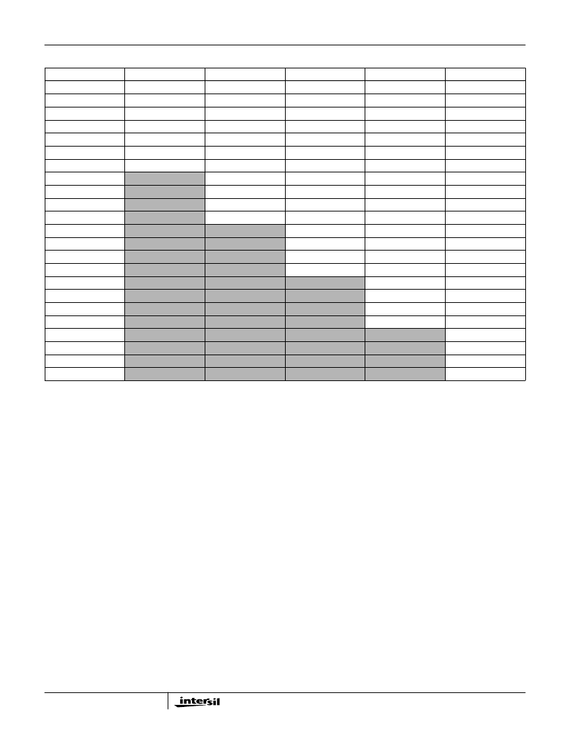
TABLE 4. HALFBAND FILTER COEFFICIENTS
COEFFICIENTS
HALFBAND #1
HALFBAND #2
HALFBAND #3
HALFBAND #4
HALFBAND #5
C0
- 0.031303406
0.005929947
-0.00130558
0.000378609
-0.000347137
C1
0.000000000
0.000000000
0.000000000
0.000000000
0.000000000
C2
0.281280518
-0.049036026
0.012379646
-0.003810883
0.00251317
C3
0.499954224
0.000000000
0.000000000
0.000000000
0.000000000
C4
0.281280518
0.29309082
-0.06055069
0.019245148
-0.010158539
C5
0.000000000
0.499969482
0.000000000
0.000000000
0.000000000
C6
- 0.031303406
0.29309082
0.299453735
-0.069904327
0.03055191
C7
0.000000000
0.499954224
0.000000000
0.000000000
C8
-0.049036026
0.299453735
0.304092407
-0.081981659
C9
0.000000000
0.000000000
0.500000000
0.000000000
C10
0.005929947
-0.06055069
0.304092407
0.309417725
C11
0.000000000
0.000000000
0.500000000
C12
0.012379646
-0.069904327
0.309417725
C13
0.000000000
0.000000000
0.000000000
C14
-0.00130558
0.019245148
-0.081981659
C15
0.000000000
0.000000000
C16
-0.003810883
0.03055191
C17
0.000000000
0.000000000
C18
0.000378609
-0.010158539
C19
0.000000000
C20
0.00251317
C21
0.000000000
C22
-0.000347137
NOTE: While Halfband filters are typically selected starting with the last stage in the filter chain to give the maximum alias free bandwidth,
a higher throughput rate may be obtained using other filter combinations. See Application Note 9720, “Calculating Maximum Pro-
cessing Rates of the PDC”.
HSP50214B
相關(guān)PDF資料 |
PDF描述 |
|---|---|
| HSP50214BVC | Programmable Downconverter |
| HSP50214BVI | Programmable Downconverter |
| HT84 | ADSL Coupling Transformers |
| HT84-00594 | ADSL Coupling Transformers |
| HT8400594S | ADSL Coupling Transformers |
相關(guān)代理商/技術(shù)參數(shù) |
參數(shù)描述 |
|---|---|
| HSP50214B_07 | 制造商:INTERSIL 制造商全稱:Intersil Corporation 功能描述:Programmable Downconverter |
| HSP50214BVC | 功能描述:上下轉(zhuǎn)換器 120L MQFP COMTEMP 14-BIT PROGRAMMABLE DOWNCONVERTER 65MSPS RoHS:否 制造商:Texas Instruments 產(chǎn)品:Down Converters 射頻:52 MHz to 78 MHz 中頻:300 MHz LO頻率: 功率增益: P1dB: 工作電源電壓:1.8 V, 3.3 V 工作電源電流:120 mA 最大功率耗散:1 W 最大工作溫度:+ 85 C 安裝風(fēng)格:SMD/SMT 封裝 / 箱體:PQFP-128 |
| HSP50214BVCZ | 功能描述:上下轉(zhuǎn)換器 120L MQFP COMTEMP 14-BIT PROG DWNCNVRT RoHS:否 制造商:Texas Instruments 產(chǎn)品:Down Converters 射頻:52 MHz to 78 MHz 中頻:300 MHz LO頻率: 功率增益: P1dB: 工作電源電壓:1.8 V, 3.3 V 工作電源電流:120 mA 最大功率耗散:1 W 最大工作溫度:+ 85 C 安裝風(fēng)格:SMD/SMT 封裝 / 箱體:PQFP-128 |
| HSP50214BVI | 功能描述:上下轉(zhuǎn)換器 120L MQFP INDTEMP 14-BIT PROGRAMMABLE DOWNCONVERTER 65MSPS RoHS:否 制造商:Texas Instruments 產(chǎn)品:Down Converters 射頻:52 MHz to 78 MHz 中頻:300 MHz LO頻率: 功率增益: P1dB: 工作電源電壓:1.8 V, 3.3 V 工作電源電流:120 mA 最大功率耗散:1 W 最大工作溫度:+ 85 C 安裝風(fēng)格:SMD/SMT 封裝 / 箱體:PQFP-128 |
| HSP50214BVIZ | 功能描述:上下轉(zhuǎn)換器 120L MQFP INDTEMP 14-BIT PROG DWNCNVRT RoHS:否 制造商:Texas Instruments 產(chǎn)品:Down Converters 射頻:52 MHz to 78 MHz 中頻:300 MHz LO頻率: 功率增益: P1dB: 工作電源電壓:1.8 V, 3.3 V 工作電源電流:120 mA 最大功率耗散:1 W 最大工作溫度:+ 85 C 安裝風(fēng)格:SMD/SMT 封裝 / 箱體:PQFP-128 |
發(fā)布緊急采購,3分鐘左右您將得到回復(fù)。