- 您現(xiàn)在的位置:買賣IC網(wǎng) > PDF目錄378516 > CYP15G0401DXA (Cypress Semiconductor Corp.) Quad HOTLink II Transceiver PDF資料下載
參數(shù)資料
| 型號: | CYP15G0401DXA |
| 廠商: | Cypress Semiconductor Corp. |
| 英文描述: | Quad HOTLink II Transceiver |
| 中文描述: | 四HOTLink II收發(fā)器 |
| 文件頁數(shù): | 21/48頁 |
| 文件大?。?/td> | 1115K |
| 代理商: | CYP15G0401DXA |
第1頁第2頁第3頁第4頁第5頁第6頁第7頁第8頁第9頁第10頁第11頁第12頁第13頁第14頁第15頁第16頁第17頁第18頁第19頁第20頁當(dāng)前第21頁第22頁第23頁第24頁第25頁第26頁第27頁第28頁第29頁第30頁第31頁第32頁第33頁第34頁第35頁第36頁第37頁第38頁第39頁第40頁第41頁第42頁第43頁第44頁第45頁第46頁第47頁第48頁
CYP15G0401DXA
PRELIMINARY
Document #: 38-02002 Rev. *B
Page 21 of 48
either a differential LVPECL clock that is DC-or AC-coupled, or
a differential LVTTL or LVCMOS clock.
By connecting the REFCLK
input to an external voltage
source or resistive voltage divider, it is possible to adjust the
reference point of the REFCLK+ input for alternate logic levels.
When doing so it is necessary to ensure that the 0V-differential
crossing point remain within the parametric range supported
by the input.
CYP15G0401DXA Receive Data Path
Serial Line Receivers
Two differential line receivers, INx1
±
and INx2
±
, are available
on each channel for accepting serial data streams. The active
line receiver on a channel is selected using the associated
INSELx input. The serial line receiver inputs are all differential,
and can accommodate wire interconnect and filtering losses
or transmission line attenuation greater than 16 dB
(V
DIF
> 100 mV, or 200 mV peak-to-peak differential) or can be
DC- or AC-coupled to +3.3V powered fiber-optic interface
modules (any ECL/PECL logic family, not limited to 100K
PECL) or AC-coupled to +5V powered optical modules. The
common-mode tolerance of these line receivers accommo-
dates a wide range of signal termination voltages. Each receiv-
er provides internal DC-restoration, to the center of the receiv-
er
’
s common mode range, for AC-coupled signals.
The local loopback input (LPEN) allows the serial transmit data
outputs to be routed internally back to the Clock and Data Re-
covery circuit associated with each channel. When configured
for local loopback, all transmit serial driver outputs are forced
to output a differential logic-1. This prevents local diagnostic
patterns from being broadcast to attached remote receivers.
Signal Detect / Link Fault
Each selected Line Receiver (i.e., that routed to the Clock and
Data Recovery PLL) is simultaneously monitored for
analog amplitude
transition density
range controls report the received data stream inside nor-
mal frequency range (± 200 ppm)
receive channel enabled
All of these conditions must be valid for the Signal Detect block
to indicate a valid signal is present. This status is presented on
the LFIx (Link Fault Indicator) output associated with each re-
ceive channel, which changes synchronous to the selected
receive interface clock.
Analog Amplitude
While the majority of these signal monitors are based on fixed
constants, the analog amplitude level detection is adjustable
to allow operation with highly attenuated signals, or in high-
noise environments. This adjustment is made through the
SDASEL signal, a 3-level select
[2]
(ternary) input, which sets
the trip point for the detection of a valid signal at one of three
levels, as listed in
Table 12
. This control input effects the ana-
log monitors for all receive channels.
The Signal Detect monitors are active for the present line re-
ceiver, as selected by the associated INSELx input. When con-
figured for local loopback (LPEN = HIGH), no line receivers are
selected, and the LFI output for each channel reports only the
receive VCO frequency out-of-range and transition density
status of the associated transmit signal. When local loopback
is active, the analog amplitude monitors are disabled.
Transition Density
The transition detection logic checks for the absence of any
transitions spanning greater than six transmission characters
(60 bits). If no transitions are present in the data received on
a channel (within the referenced period), the transition detec-
tion logic for that channel will assert LFIx. The LFIx output
remains asserted until at least one transition is detected in
each of three adjacent received characters.
Range Controls
The receive-VCO range-control monitors do more than just
report the frequency status of the received signal. They also
determine if the receive Clock/Data Recovery circuits (CDR)
should align the receive VCO clock to the data stream or to the
local REFCLK input. This function prevents the receive VCO
from tracking an out-of-specification received signal.
When the range-control monitor for a channel indicates that
the signaling rate is within specification, the phase detector in
the receive PLL is configured to track the transitions in the
received data stream. In this mode the LFIx output for the as-
sociated channel is HIGH (unless one of the other status mon-
itors indicates that the received signal is out of specification).
If the range-control monitor indicates that the received data
stream signaling-rate is out of specification, the phase detector
is configured to track the local REFCLK input, and the associ-
ated LFIx output is asserted LOW.
The specific trip points for this compare function are listed in
Table 13
. Because the compare function operates with two
asynchronous clocks, there is a small uncertainty in the mea-
surement. The switch points are asymmetric to provide hyster-
esis to the operation.
Receive Channel Enabled
The CYP15G0401DXA contains four receive channels that
can be independently enabled and disabled. Each channel
can be enabled or disabled separately through the BOE[7:0]
inputs, as controlled by the RXLE latch-enable signal. When
RXLE is HIGH, the signals present on the BOE[7:0] inputs are
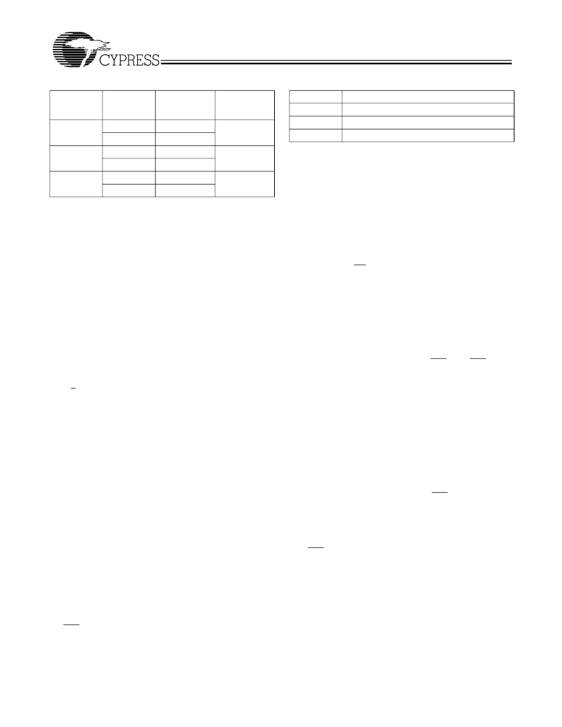
Table 11. Operating Speed Settings
SPDSEL
LOW
TXRATE
1
0
1
0
1
0
REFCLK
Frequency
(MHz)
10
–
20
20
–
40
20
–
40
40
–
80
40
–
75
80
–
150
Signaling
Rate
(MBaud)
200
–
400
MID (Open)
400
–
800
HIGH
800
–
1500
Table 12. Analog Amplitude Detect Valid Signal Levels
SDASEL
LOW
MID (Open)
HIGH
Typical signal with peak amplitudes above
140 mV p-p differential
280 mV p-p differential
420 mV p-p differential
相關(guān)PDF資料 |
PDF描述 |
|---|---|
| CYP15G0401DXB | PREMIUM VGA CABLE W/AUDIO3FT, HD15 & 3.5MM M-M |
| CYP15G0401DXB-BGC | PREMIUM VGA CABLE W/AUDIO5FT, HD15 & 3.5MM M-M |
| CYP15G0401DXB-BGI | Quad HOTLink II Transceiver |
| CYP15G0401DXA-BGC | Quad HOTLink II Transceiver |
| CYP15G0401DXA-BGI | Quad HOTLink II Transceiver |
相關(guān)代理商/技術(shù)參數(shù) |
參數(shù)描述 |
|---|---|
| CYP15G0401DXA-BGC | 制造商:CYPRESS 制造商全稱:Cypress Semiconductor 功能描述:Quad HOTLink II Transceiver |
| CYP15G0401DXA-BGI | 制造商:CYPRESS 制造商全稱:Cypress Semiconductor 功能描述:Quad HOTLink II Transceiver |
| CYP15G0401DXB | 制造商:CYPRESS 制造商全稱:Cypress Semiconductor 功能描述:Quad HOTLink II Transceiver |
| CYP15G0401DXB_05 | 制造商:CYPRESS 制造商全稱:Cypress Semiconductor 功能描述:Quad HOTLink II⑩ Transceiver |
| CYP15G0401DXB-BGC | 功能描述:電信線路管理 IC Dual Channel XCVR 1.5Gbps Bckplane COM RoHS:否 制造商:STMicroelectronics 產(chǎn)品:PHY 接口類型:UART 電源電壓-最大:18 V 電源電壓-最小:8 V 電源電流:30 mA 最大工作溫度:+ 85 C 最小工作溫度:- 40 C 安裝風(fēng)格:SMD/SMT 封裝 / 箱體:VFQFPN-48 封裝:Tray |
發(fā)布緊急采購,3分鐘左右您將得到回復(fù)。