- 您現(xiàn)在的位置:買賣IC網(wǎng) > PDF目錄369679 > CYNSE70256 Network Processing PDF資料下載
參數(shù)資料
| 型號: | CYNSE70256 |
| 英文描述: | Network Processing |
| 中文描述: | 網(wǎng)絡處理 |
| 文件頁數(shù): | 115/126頁 |
| 文件大小: | 3302K |
| 代理商: | CYNSE70256 |
第1頁第2頁第3頁第4頁第5頁第6頁第7頁第8頁第9頁第10頁第11頁第12頁第13頁第14頁第15頁第16頁第17頁第18頁第19頁第20頁第21頁第22頁第23頁第24頁第25頁第26頁第27頁第28頁第29頁第30頁第31頁第32頁第33頁第34頁第35頁第36頁第37頁第38頁第39頁第40頁第41頁第42頁第43頁第44頁第45頁第46頁第47頁第48頁第49頁第50頁第51頁第52頁第53頁第54頁第55頁第56頁第57頁第58頁第59頁第60頁第61頁第62頁第63頁第64頁第65頁第66頁第67頁第68頁第69頁第70頁第71頁第72頁第73頁第74頁第75頁第76頁第77頁第78頁第79頁第80頁第81頁第82頁第83頁第84頁第85頁第86頁第87頁第88頁第89頁第90頁第91頁第92頁第93頁第94頁第95頁第96頁第97頁第98頁第99頁第100頁第101頁第102頁第103頁第104頁第105頁第106頁第107頁第108頁第109頁第110頁第111頁第112頁第113頁第114頁當前第115頁第116頁第117頁第118頁第119頁第120頁第121頁第122頁第123頁第124頁第125頁第126頁

CYNSE70032
Document #: 38-02042 Rev. *E
Page 115 of 126
18.0
JTAG (1149.1) Testing
The CYNSE70032 supports the Test Access Port (TAP) and Boundary Scan Architecture, as specified in the IEEE JTAG standard
1149.1. The pin interface to the chip consists of five signals with the standard definitions: TCK, TMS, TDI, TDO, and TRST_L.
Table 18-1
describes the operations that the test access port controller supports, and
Table 18-2
describes the TAP Device ID
Register.
Note
. To disable JTAG functionality, connect the TCK, TMS and TDI pins to V
DDQ
through a pull-up, and TRST_L to
ground through a pull-down.
Table 18-1. Supported Operations
Instruction
SAMPLE/PRELOAD
Type
Description
Mandatory
Sample/Preload
. This operation loads the values of signals going to and from I/O
pins into the boundary scan shift register to provide a snapshot of the normal
functional operation, and to initialize the boundary scan.
External Test
. This operation uses boundary scan values shifted in from TAP to
test connectivity external to the device.
This operation loads a single bit shift register between TDI and TDO
and
provides a minimum-length serial path when no test operation is required.
This operation selects the Identification register between TDI and TDO
and
allows the “idcode” to be read serially through TDO.
This operation drives preset values onto the outputs of devices
.
This operation leaves the device output pins in a high impedance state
.
EXTEST
Mandatory
BYPASS
Mandatory
IDCODE
Optional
CLAMP
HIghZ
Optional
Optional
Pogam
Memoy
Network Line Interfaces
System Bus
Pocesso
Swtch
Fabic
ASC
Seach
Engne
SRBank
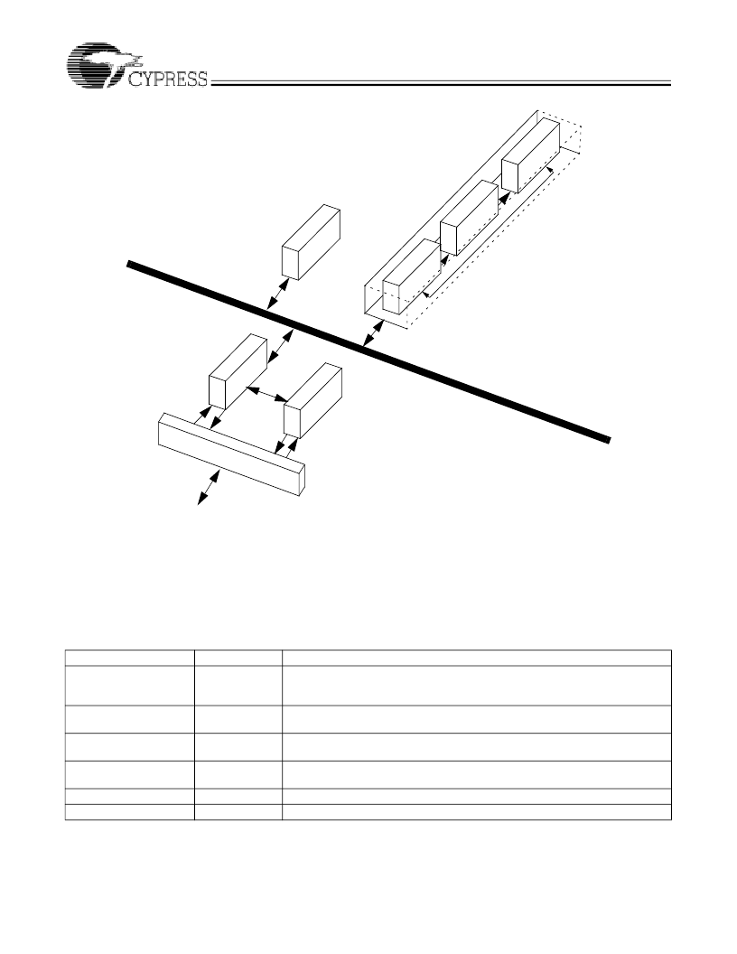
Figure 17-1. Sample Switch/Router Using the CYNSE70032 Device
相關PDF資料 |
PDF描述 |
|---|---|
| CZET101 | Clock Driver |
| CZEU101 | Quad Peripheral Driver |
| CZEZ101 | Triple Peripheral Driver |
| CZSP103 | Voltage Reference |
| CZT122 | TRANSISTOR | BJT | DARLINGTON | NPN | 100V V(BR)CEO | 5A I(C) | SOT-223 |
相關代理商/技術參數(shù) |
參數(shù)描述 |
|---|---|
| CYNSE70256-66BGC | 制造商:Cypress Semiconductor 功能描述: |
| CYNSE70256-66BHC | 制造商:Cypress Semiconductor 功能描述:COMMUNICATIONS, NETWORK SEARCH ENGINE - Trays |
| CYONS10017-LBXC | 制造商:Cypress Semiconductor 功能描述: |
| CYONS1001G-LBXC | 制造商:Cypress Semiconductor 功能描述: 制造商:Rochester Electronics LLC 功能描述: |
| CYONS1001L | 制造商:CYPRESS 制造商全稱:Cypress Semiconductor 功能描述:OvationONS⑩ 1L - Laser Navigation Sensor |
發(fā)布緊急采購,3分鐘左右您將得到回復。