- 您現(xiàn)在的位置:買賣IC網(wǎng) > PDF目錄378513 > CY7C924ADX (Cypress Semiconductor Corp.) 200 MBaud HOTLink Transceiver(200MBaud HOTLink收發(fā)器) PDF資料下載
參數(shù)資料
| 型號: | CY7C924ADX |
| 廠商: | Cypress Semiconductor Corp. |
| 英文描述: | 200 MBaud HOTLink Transceiver(200MBaud HOTLink收發(fā)器) |
| 中文描述: | 200 MBd的的HOTLink收發(fā)器(200MBaud的HOTLink收發(fā)器) |
| 文件頁數(shù): | 22/58頁 |
| 文件大小: | 969K |
| 代理商: | CY7C924ADX |
第1頁第2頁第3頁第4頁第5頁第6頁第7頁第8頁第9頁第10頁第11頁第12頁第13頁第14頁第15頁第16頁第17頁第18頁第19頁第20頁第21頁當前第22頁第23頁第24頁第25頁第26頁第27頁第28頁第29頁第30頁第31頁第32頁第33頁第34頁第35頁第36頁第37頁第38頁第39頁第40頁第41頁第42頁第43頁第44頁第45頁第46頁第47頁第48頁第49頁第50頁第51頁第52頁第53頁第54頁第55頁第56頁第57頁第58頁
CY7C924ADX
Document #: 38-02008 Rev. *E
Page 22 of 58
being LOW (0). This allows the standard Special Characters
codes to also be reported and output.
Individual character errors that are not part of one of the
supported sequences (Start of Cell, Extended Command, or
Serial Address) are marked by the 011b (RXSOC = 0,
RXSC/D* = 1, and RXRVS = 1) decode status.
Anytime RXSOC is reported HIGH (1) at least one of the C8.0,
C9.0, or C10.0 characters was received as a valid character.
If the immediately following character is a valid Data character,
then the corresponding combination of RXSOC, RXSC/D*,
and RXRVS indicate the type of information received. If the
immediately following character is a Special Character code of
any type (even a C5.0), then a 101b is posted to indicate an
illegal sequence was received.
An illegal sequence can be caused by a remote transmitter
sending incorrect information, or by receiving data corrupted
during transmission. When such an error is detected, the 101b
status bits are posted and the associated data field is set to the
Special Character code that was received without error (C8.0,
C9.0, or C10.0 reported as D8.0, D9.0, or D10.0 along with the
101b status). This information is provided to assist in
debugging link or protocol faults.
The 100b indication is used to mark the associated Data
character as the first character of a new frame, packet, cell, or
other data construct used by the system. The Data characters
and Special Character codes that follow this marker are written
to the Receive FIFO (if the present address matching require-
ments are satisfied).
The 110b indication is used to mark the associated data
character as the first character of an extended command. In
reality there is no limit to the number of immediately following
data characters that can be considered part of this command.
The most common interpretation is based on the configured
bus width, such that single-character configurations support
the associated character as the extended command, providing
up to 256 extended commands for 8-bit data and 1024 for
10-bit byte-packed data.
This marker is treated internally the same as the 100b Start Of
Cell indication, which allows it to be used to mark the boundary
of any user-specific information. As a boundary or cell marker,
the immediately following data can be a data field, a header, a
stream identifier, a transaction number, a packet length
indicator, or any of a number of pieces of information
connected to a data transfer.
Note
. In reality, the 100b and 110b indicators can be used
interchangeably; i.e., the 100b indication can be used to mark
extended commands while the 110b indication can be used to
mark the start of cells.
The 111b indication is used to mark the start of a Serial
Address field. Unlike the Start Of Cell and Extended Command
markers, which have no specific data-field length associated
with them, the associated Serial Address is always comprised
of the immediately following single data character, and
supports a fixed 8-bit or 10-bit address field format in 8-bit or
10-bit byte-packed data formats.
When this serial address is received it may be passed to the
Receive FIFO or discarded (see
Table 7 on page 23
).
Address Matching
For those modes where address matching is enabled, the
CY7C924ADX’s ability to accept or discard data can be
controlled by the remote transmitter. This is often useful in
configurations with one or more data sources and multiple
data destinations.
Each CY7C924ADX contains an 8-bit or 10-bit Serial Address
Register that is compared with the first data character received
following a Serial Address marker (C10.0). This character
constitutes an address, which can be configured for one of two
modes for address matching. The first mode is used for
multicast addresses, where a bit-wise AND is performed on
each bit of the address character received, with the contents
of each of the bits in the Serial Address Register. If any of the
same bit locations in the register and the received data are
both set to ‘1’, a multicast address match is declared and the
following data and Special Character codes are interpreted
and passed to the Receive FIFO.
If the multicast address field is ever received as all 1s (FFh or
3FFh), the receiver always accepts the data. This all 1s setting
is the broadcast address and is used to send data to all
receivers.
This all 1s setting also has special meaning when written to
the Serial Address Register. When the multicast address field
is written to an all 1s (FFh or 3FFh) state, the receiver operates
in promiscuous mode, and receives all data, regardless of the
contents of any serial address commands received. This is
also the default or power-up state of the Serial Address
register.
The second mode of operation for address matching is when
the Serial Address register contains a unique device address,
and is compared with the character received following the
C10.0 Serial Address marker. This unicast address requires
an exact match between all 8 or 10 bits to declare a match
found and allow the following data to pass.
When the Elasticity Buffer is enabled, all received characters
(except C5.0) are written to the Elasticity Buffer, regardless of
the state or configuration of any present address match. This
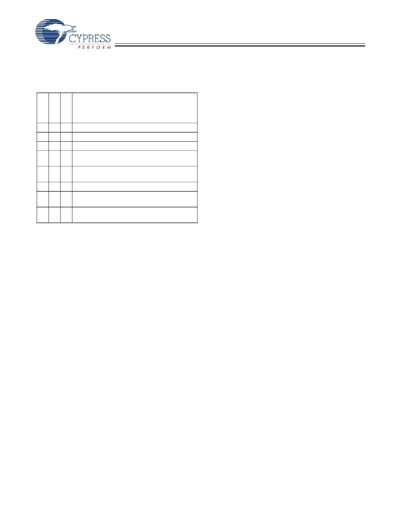
Table 6. Receive Data Formatting
R
R
R
Data Format Indication
0
0
0
0
0
0
1
1
0
1
0
1
Normal Data Character
Reserved
Normal Command Character
Received C0.7 Exception Character or Other
Character Exception (as listed in
Table 12
)
Received Start of Cell Marker (C8.0) + Data
Character
Received Illegal Sequence
Received Extended Command Marker (C9.0) +
Data Character (interpreted as a command)
Received Serial Address Marker (C10.0) + Data
Character (interpreted as an address)
1
0
0
1
1
0
1
1
0
1
1
1
相關PDF資料 |
PDF描述 |
|---|---|
| CY7C924DX | 200-MBaud HOTLink Transceiver(200H波特熱接插收發(fā)器) |
| CY7C954DX | ATM HOTLink Transceiver(ATM 熱接插收發(fā)器) |
| CY7C964A | Bus Interface Logic Circuit |
| CY7C964A-UM | Bus Interface Logic Circuit |
| CY7C964A-UMB | Bus Interface Logic Circuit |
相關代理商/技術參數(shù) |
參數(shù)描述 |
|---|---|
| CY7C924ADX-AC | 制造商:Rochester Electronics LLC 功能描述: 制造商:Cypress Semiconductor 功能描述: |
| CY7C924ADX-ADI | 制造商:Rochester Electronics LLC 功能描述: 制造商:Cypress Semiconductor 功能描述: |
| CY7C924ADX-AI | 制造商:Cypress Semiconductor 功能描述:Framer 5V 100-Pin TQFP |
| CY7C924ADX-AXC | 功能描述:網(wǎng)絡控制器與處理器 IC HOTLink DX COM RoHS:否 制造商:Micrel 產(chǎn)品:Controller Area Network (CAN) 收發(fā)器數(shù)量: 數(shù)據(jù)速率: 電源電流(最大值):595 mA 最大工作溫度:+ 85 C 安裝風格:SMD/SMT 封裝 / 箱體:PBGA-400 封裝:Tray |
| CY7C924ADX-AXCKJ | 制造商:Cypress Semiconductor 功能描述: |
發(fā)布緊急采購,3分鐘左右您將得到回復。