- 您現(xiàn)在的位置:買賣IC網(wǎng) > PDF目錄375384 > AX88796BLI (ASIX Electronics Corporation) Low-pin-count Non-PCI 8/16-bit 10/100M Fast Ethernet Controller PDF資料下載
參數(shù)資料
| 型號: | AX88796BLI |
| 廠商: | ASIX Electronics Corporation |
| 英文描述: | Low-pin-count Non-PCI 8/16-bit 10/100M Fast Ethernet Controller |
| 中文描述: | 低引腳數(shù)的非PCI 16位產(chǎn)品10/100M自適應快速以太網(wǎng)控制器 |
| 文件頁數(shù): | 13/82頁 |
| 文件大小: | 519K |
| 代理商: | AX88796BLI |
第1頁第2頁第3頁第4頁第5頁第6頁第7頁第8頁第9頁第10頁第11頁第12頁當前第13頁第14頁第15頁第16頁第17頁第18頁第19頁第20頁第21頁第22頁第23頁第24頁第25頁第26頁第27頁第28頁第29頁第30頁第31頁第32頁第33頁第34頁第35頁第36頁第37頁第38頁第39頁第40頁第41頁第42頁第43頁第44頁第45頁第46頁第47頁第48頁第49頁第50頁第51頁第52頁第53頁第54頁第55頁第56頁第57頁第58頁第59頁第60頁第61頁第62頁第63頁第64頁第65頁第66頁第67頁第68頁第69頁第70頁第71頁第72頁第73頁第74頁第75頁第76頁第77頁第78頁第79頁第80頁第81頁第82頁
ASIX ELECTRONICS CORPORATION
13
AX88796BLF / AX88796BLI
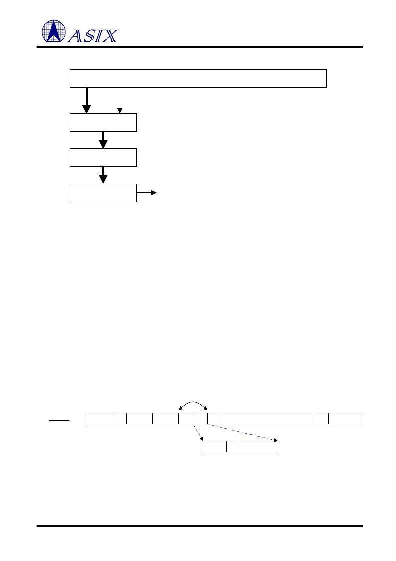
If address Y is found to hash to the value 32 (20H), then FB32 (ref. 4.1.2) in MAR2 should be initialized to ``1''. This
will cause the AX88796B to accept any multicast packet with the address Y.
Although the hashing algorithm does not guarantee perfect filtering of multicast address, it will perfectly filter up to
64 logical address filters if these addresses are chosen to map into unique locations in the multicast filter.
Note:
The first bit of received packet sequence is 1’s stands by Multicast Address.
4.1.3 Broadcast Address Match Filter
The Broadcast check logic compares the Destination Address Field (first 6 bytes of the received packet) to all 1’s,
which is the values are “FF FF FF FF FF FF FF” in Hex format. If any bit of the six bytes does not equal to 1’s, the
Protocol Control Logic rejects the packet.
4.1.4 VLAN Match Filter
AX88796B compares the thirteenth and fourteenth bytes of receive frames. If not match with VLAN_ID1,
VLAN_ID_0 (offset 1dh, 1ch) then reject current frame. The VLAN filter will always accept VLAN_ID is zero of
receive frames due to it is 802.1q (for priority purpose) frames. The maximum length of the good packet is thus
change from 1518 bytes to 1522 bytes.
32-bit CRC Generator
Latch
1 of 64-bit decoder
Filter bit array
X=31 to X=26
Clock
Selected bit
0 = reject, 1= accept
7 Bytes
Preamble
SFD
1 Byte
6 Bytes
Destination
Address
6 Bytes
Source
Address
2 B
46-1500 Bytes
4 Bytes
L/T
Data
Pad
FCS
Layer 2
Frame (64-1518 Bytes)
VLAN (64-1522 Bytes)
8100
TCI
2 B
2 B
VLAN ID
Priority
CFI
802.1Q
VLAN tagging
3 bits
12 bits
1 bit
相關PDF資料 |
PDF描述 |
|---|---|
| AX88872P | 10/100BASE Dual Speed “Swipeater” Controller |
| AX9902MS | 2N and 2P-Channel Enhancement Mode Power MOSFET |
| AX9902MSA | 2N and 2P-Channel Enhancement Mode Power MOSFET |
| AXC-051 | ACTIVE FILTER FOR RIPPLE ATTENUATION 5A |
| AXC-051-R | ACTIVE FILTER FOR RIPPLE ATTENUATION 5A |
相關代理商/技術參數(shù) |
參數(shù)描述 |
|---|---|
| AX88796C | 制造商:ASIX 制造商全稱:ASIX 功能描述:Low-Power SPI or Non-PCI Ethernet Controller |
| AX88796CLF | 制造商:ASIX Electronics Corporation 功能描述: |
| AX88796L | 制造商:ASIX 制造商全稱:ASIX 功能描述:3-in-1 Local Bus Fast Ethernet Controller |
| AX88796LF | 制造商:ASIX 功能描述:10/100 MAC |
| AX88850 | 制造商:ASIX 制造商全稱:ASIX 功能描述:100BASE-TX/FX Repeater Controller |
發(fā)布緊急采購,3分鐘左右您將得到回復。