- 您現(xiàn)在的位置:買(mǎi)賣(mài)IC網(wǎng) > PDF目錄166131 > AK4665AEN SPECIALTY CONSUMER CIRCUIT, QCC32 PDF資料下載
參數(shù)資料
| 型號(hào): | AK4665AEN |
| 元件分類: | 消費(fèi)家電 |
| 英文描述: | SPECIALTY CONSUMER CIRCUIT, QCC32 |
| 封裝: | 5 X 5 MM, 0.50 MM PITCH, LEAD FREE, QFN-32 |
| 文件頁(yè)數(shù): | 51/52頁(yè) |
| 文件大?。?/td> | 522K |
| 代理商: | AK4665AEN |
第1頁(yè)第2頁(yè)第3頁(yè)第4頁(yè)第5頁(yè)第6頁(yè)第7頁(yè)第8頁(yè)第9頁(yè)第10頁(yè)第11頁(yè)第12頁(yè)第13頁(yè)第14頁(yè)第15頁(yè)第16頁(yè)第17頁(yè)第18頁(yè)第19頁(yè)第20頁(yè)第21頁(yè)第22頁(yè)第23頁(yè)第24頁(yè)第25頁(yè)第26頁(yè)第27頁(yè)第28頁(yè)第29頁(yè)第30頁(yè)第31頁(yè)第32頁(yè)第33頁(yè)第34頁(yè)第35頁(yè)第36頁(yè)第37頁(yè)第38頁(yè)第39頁(yè)第40頁(yè)第41頁(yè)第42頁(yè)第43頁(yè)第44頁(yè)第45頁(yè)第46頁(yè)第47頁(yè)第48頁(yè)第49頁(yè)第50頁(yè)當(dāng)前第51頁(yè)第52頁(yè)

ASAHI KASEI
[AK4665A]
MS0440-E-01
2006/05
- 8 -
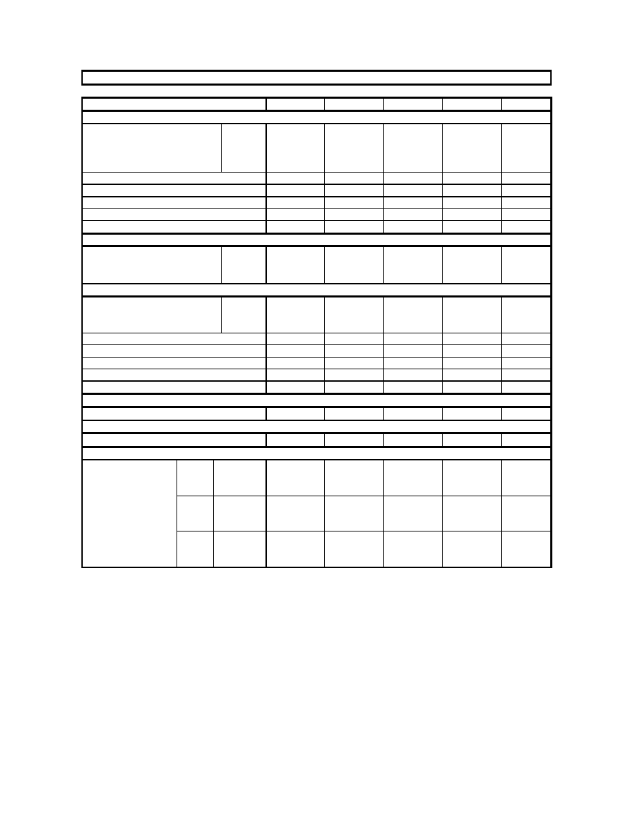
FILTER CHARACTERISTICS
(Ta=25
°C; AVDD, DVDD, HVDD=2.6 3.6V; TVDD=1.6 3.6V; fs=44.1kHz; DEM=OFF; BOOST=OFF)
Parameter
Symbol
min
typ
max
Units
ADC Digital Filter (LPF):
Passband (Note 13)
±0.16dB
PB
0
-
17.3
kHz
0.66dB
-
19.4
-
kHz
1.1dB
-
19.9
-
kHz
6.9dB
-
22.1
-
kHz
Stopband (Note 13)
SB
26.1
-
kHz
Passband Ripple
PR
-
±0.1
dB
Stopband Attenuation
SA
73
-
dB
Group Delay (Note 14)
GD
-
17
-
1/fs
Group Delay Distortion
GD
-
0
-
s
ADC Digital Filter (HPF):
Frequency Response (Note 13)
3dB
FR
-
3.4
-
Hz
0.5dB
-
10
-
Hz
0.1dB
-
22
-
Hz
DAC Digital Filter: (Note 15)
Passband (Note 13)
±0.1dB
PB
0
-
19.6
kHz
0.7dB
-
20.0
-
kHz
6.0dB
-
22.05
-
kHz
Stopband (Note 13)
SB
25.2
-
kHz
Passband Ripple
PR
-
±0.01
dB
Stopband Attenuation
SA
59
-
dB
Group Delay (Note 14)
GD
-
17.5
-
1/fs
Group Delay Distortion
GD
-
0
-
s
DAC Digital Filter + Analog Filter: (Note 15)
Frequency Response: 0
20.0kHz
FR
-
±1.0
-
dB
Analog Filter: (Note 16)
Frequency Response: 0
20.0kHz
FR
-
±1.0
-
dB
BOOST Filter: (Note 17)
Frequency Response
20Hz
FR
-
5.76
-
dB
MIN
100Hz
-
2.92
-
dB
1kHz
-
0.02
-
dB
20Hz
FR
-
10.80
-
dB
MID
100Hz
-
6.84
-
dB
1kHz
-
0.13
-
dB
20Hz
FR
-
16.06
-
dB
MAX
100Hz
-
10.54
-
dB
1kHz
-
0.37
-
dB
Note 13. The passband and stopband frequencies scale with fs.
For example (DAC), PB=0.44*fs(@
±0.1dB), SB=0.57*fs(@59dB).
Note 14. This is the calculated delay time caused by digital filtering. This time is measured from the input of analog signal
to setting the 20 bit data of both channels on input register to the output register of ADC. For DAC, this time is
from setting the 20 bit data of both channels on input register to the output of analog signal.
Note 15. BOOST OFF (BST1-0 bits = “00”)
Note 16. LIN
→HPL, RIN→HPR, MIN→HPL/HPR.
Note 17. These frequency responses scale with fs. If high-level signal is input, the AK4665A clips at low frequency.
相關(guān)PDF資料 |
PDF描述 |
|---|---|
| AK5368192WP-80 | 8M X 36 FAST PAGE DRAM MODULE, 80 ns, SMA72 |
| AK5385A | 24BIT 192KHZ ADC |
| AK8406A | AK8406A |
| AK8432 | 6CH 10bit 40MSPS】3 |
| AK8850 | NTSC Digital Video Decoder |
相關(guān)代理商/技術(shù)參數(shù) |
參數(shù)描述 |
|---|---|
| AK4666VQ | 功能描述:IC CODEC STEREO 20BIT LQFP 制造商:akm semiconductor inc. 系列:* 零件狀態(tài):上次購(gòu)買(mǎi)時(shí)間 標(biāo)準(zhǔn)包裝:1,000 |
| AK4671 | 制造商:AKM 制造商全稱:AKM 功能描述:Stereo CODEC with MIC/RCV/HP-AMP |
| AK4671_10 | 制造商:AKM 制造商全稱:AKM 功能描述:Stereo CODEC with MIC/RCV/HP-AMP |
| AK4671EG | 制造商:AKM 制造商全稱:AKM 功能描述:Stereo CODEC with MIC/RCV/HP-AMP |
| AK4673 | 制造商:AKM 制造商全稱:AKM 功能描述:Stereo CODEC with MIC/HP-AMP and Touch Screen Controller |
發(fā)布緊急采購(gòu),3分鐘左右您將得到回復(fù)。