- 您現(xiàn)在的位置:買賣IC網(wǎng) > PDF目錄373859 > AD1816AJS (ANALOG DEVICES INC) SoundPort Controller PDF資料下載
參數(shù)資料
| 型號: | AD1816AJS |
| 廠商: | ANALOG DEVICES INC |
| 元件分類: | 消費家電 |
| 英文描述: | SoundPort Controller |
| 中文描述: | SPECIALTY CONSUMER CIRCUIT, PQFP100 |
| 封裝: | PLASTIC, QFP-100 |
| 文件頁數(shù): | 24/52頁 |
| 文件大小: | 477K |
| 代理商: | AD1816AJS |
第1頁第2頁第3頁第4頁第5頁第6頁第7頁第8頁第9頁第10頁第11頁第12頁第13頁第14頁第15頁第16頁第17頁第18頁第19頁第20頁第21頁第22頁第23頁當前第24頁第25頁第26頁第27頁第28頁第29頁第30頁第31頁第32頁第33頁第34頁第35頁第36頁第37頁第38頁第39頁第40頁第41頁第42頁第43頁第44頁第45頁第46頁第47頁第48頁第49頁第50頁第51頁第52頁

AD1816A
–24–
REV. A
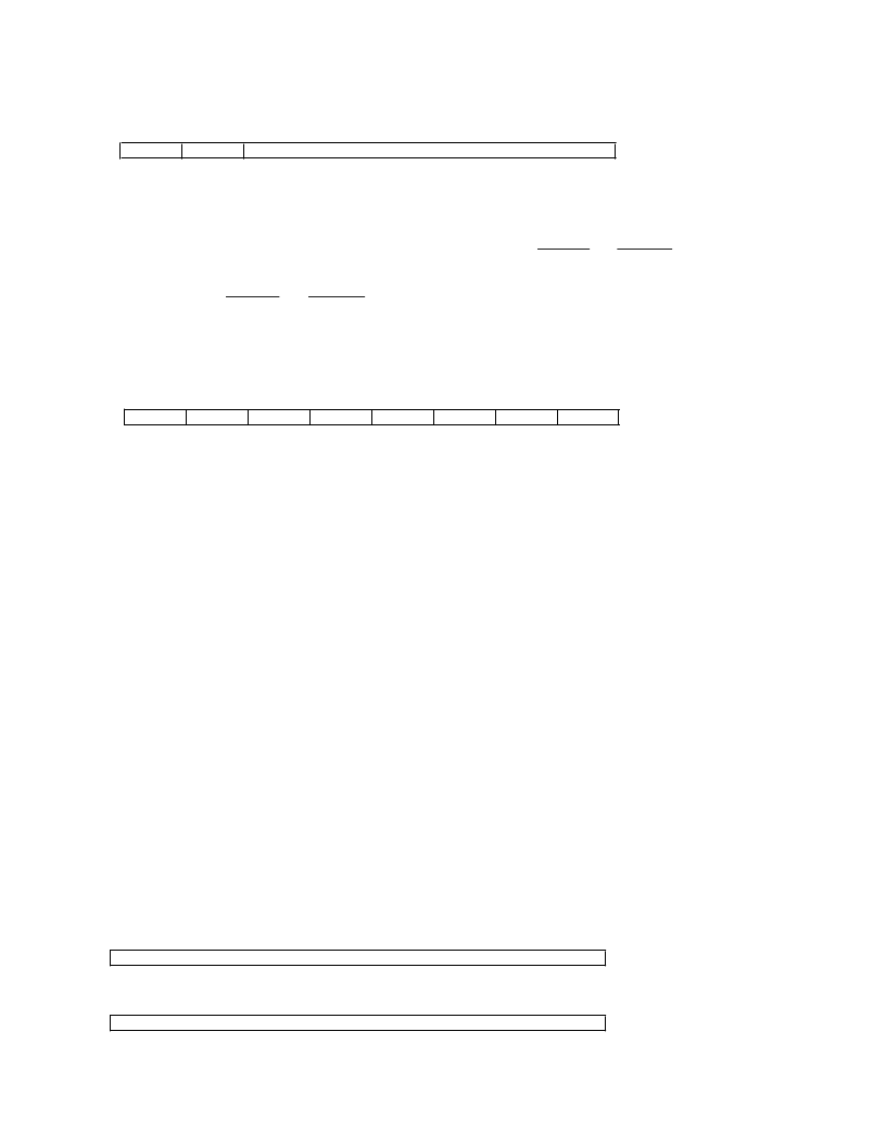
[Base+0]
Chip Status/Indirect Address
7
6
5
4
3
2
1
0
CRDY
VBL
INADR[5:0]
RESET = [0x00]
INADR [5:0] (RW) Indirect Address for Sound System (SS). T hese bits are used to access the Indirect Registers shown in T able VIII.
All registers data must be written in pairs, low byte followed by high byte, by loading the Indirect SS Data
Registers, (Base +2) and (Base +3).
VBL
Volume Button Location. When using an EEPROM to configure the PnP state of the AD1816A, this bit determines
whether PQFP Pins 1 and 2 (T QFP Pins 99 and 100) are used for
VOL_UP
and
VOL_DN
or I
2
S0_DAT A and
I
2
S0_LRCLK respectively.
0
I
2
S0_DAT A and I
2
S0_LRCLK
1
VOL_UP
and
VOL_DN
CRDY
(RO) AD1816A Ready. T he AD1816A asserts this bit when AD1816A can accept data.
0
AD1816A not ready
1
AD1816A ready
[Base+1]
Interrupt Status
7
PI
6
5
4
3
2
1
0
SI
CI
T I
VI
DI
RI
GI
RESET = [0x00]
SI
(RO) SoundBlaster generated Interrupt.
0
No interrupt
1
SoundBlaster interrupt pending
(RW) Game Interrupt (Sticky, Write “0” to Clear).
0
No interrupt
1
An interrupt is pending due to Digital Game Port data ready
(RW) Ring Interrupt (Sticky, Write “0” to Clear).
0
No interrupt
1
An interrupt is pending due to a Hardware Ring pin being asserted
(RW) DSP Interrupt (Sticky, Write “0” to Clear).
0
No interrupt
1
An interrupt is pending due to a write to the DIT bit in indirect register [33] bit <13>
(RW) Volume Interrupt (Sticky, Write “0” to Clear).
0
No interrupt
1
An interrupt is pending due to Hardware Volume Button being pressed
(RW) T imer Interrupt. T his bit indicates there is an interrupt pending from the timer count registers. (Sticky,
Write “0” to Clear).
0
No interrupt
1
Interrupt is pending from the timer count register
(RW) Capture Interrupt. T his bit indicates that there is an interrupt pending from the capture DMA count register.
(Sticky, Write “0” to Clear).
0
No interrupt
1
Interrupt is pending from the capture DMA count register
(RW) Playback Interrupt. T his bit indicates that there is an interrupt pending from the playback DMA count
register. (Sticky, Write “0” to Clear).
0
No interrupt
1
Interrupt is pending from the playback DMA count register
GI
RI
DI
VI
T I
CI
PI
[Base+2]
Indirect SS Data Low Byte
7
6
5
4
3
2
1
0
Indirect SS Data [7:0]
RESET = [0xX X ]
[Base+3]
Indirect SS Data High Byte
7
6
5
4
3
2
1
0
Indirect SS Data [15:8]
RESET = [0xX X ]
Indirect SS
Data [15:0]
Indirect Sound System Data. Data in this register is written to the Sound System Indirect Register specified by the
address contained in INDAR [5:0], Sound System Direct Register [Base +0]. Data is written when the Indirect SS
Data High Byte value is loaded.
相關(guān)PDF資料 |
PDF描述 |
|---|---|
| AD1816AJST | SoundPort Controller |
| AD1816A | SoundPort Controller(數(shù)字音頻的聲音端口控制器) |
| AD1818 | PCI SoundComm DC97 Digital Controller(PCI SoundComm DC97型數(shù)字控制器) |
| AD1819A | AC97 SoundPort Codec(AC97型聲音端口信號編解碼器) |
| AD1819BJST | AC’97 SoundPort Codec |
相關(guān)代理商/技術(shù)參數(shù) |
參數(shù)描述 |
|---|---|
| ad1816ajs-eeprom | 制造商:Rochester Electronics LLC 功能描述:AD1816A SOUND PORT CONTRO - Bulk 制造商:Analog Devices 功能描述: |
| AD1816AJST | 制造商:AD 制造商全稱:Analog Devices 功能描述:SoundPort Controller |
| ad1816js3 | 制造商:Rochester Electronics LLC 功能描述:- Bulk 制造商:Analog Devices 功能描述: |
| AD18-182 | 制造商:Thomas & Betts 功能描述:Terminal; 22 to 18 AWG; Brass; Non-Insulated; Tin Plated; UL 94V-2 制造商:Thomas & Betts 功能描述:DISCONNECTFEMALE 制造商:Thomas & Betts 功能描述:Quick Disconnect Terminal 18-22AWG F 21.08mm 5.84mm Tin |
| AD18-183 | 制造商:Thomas & Betts 功能描述:Terminal; 22 to 18 AWG; Brass; Nylon; Tin Plated; UL 94V-2 制造商:Thomas & Betts 功能描述:NON-INS FEM-187 DISC, 22-18 LEN .64 制造商:Thomas & Betts 功能描述:Quick Disconnect Terminal 18-22AWG F 16.26mm 5.84mm Tin |
發(fā)布緊急采購,3分鐘左右您將得到回復。