- 您現(xiàn)在的位置:買賣IC網(wǎng) > PDF目錄373859 > AD1816AJS (ANALOG DEVICES INC) SoundPort Controller PDF資料下載
參數(shù)資料
| 型號: | AD1816AJS |
| 廠商: | ANALOG DEVICES INC |
| 元件分類: | 消費家電 |
| 英文描述: | SoundPort Controller |
| 中文描述: | SPECIALTY CONSUMER CIRCUIT, PQFP100 |
| 封裝: | PLASTIC, QFP-100 |
| 文件頁數(shù): | 20/52頁 |
| 文件大小: | 477K |
| 代理商: | AD1816AJS |
第1頁第2頁第3頁第4頁第5頁第6頁第7頁第8頁第9頁第10頁第11頁第12頁第13頁第14頁第15頁第16頁第17頁第18頁第19頁當前第20頁第21頁第22頁第23頁第24頁第25頁第26頁第27頁第28頁第29頁第30頁第31頁第32頁第33頁第34頁第35頁第36頁第37頁第38頁第39頁第40頁第41頁第42頁第43頁第44頁第45頁第46頁第47頁第48頁第49頁第50頁第51頁第52頁
AD1816A
–20–
REV. A
PNPR
Plug and Play Reset flag. T his bit is set by an AD1816A reset (RESET B pin asserted LOW) or by a Plug and Play
reset command. T his bit is cleared by the assertion of the FCLR bit in the control word. While this bit is set, all at-
tempts to write an SS indirect register via the DSP port will be ignored and fail. T his is to ensure that Plug and
Play resets are immediately applied to the application running on the DSP, without requiring them to continuously poll
the Plug and Play reset status bit. During the frame in which this bit is cleared (by asserting FCLR), an attempt to
write an SS indirect register will succeed. If the FCLR bit is continuously asserted, writes to indirect registers via
the DSP port will always be enabled. A Plug and Play reset command will set this PNPR bit HIGH during at least
one frame.
Power-Down flag. T his bit is set by an AD1816A reset (RESET B pin asserted LOW), or by an AD1816A power-
down. Before an AD1816A power-down sequence shuts down the DSP port, at least one frame will be sent with
this bit set. T his bit can be cleared by the assertion of the FCLR (DSP port status clear) bit in the control word,
providing the AD1816A is no longer in power-down.
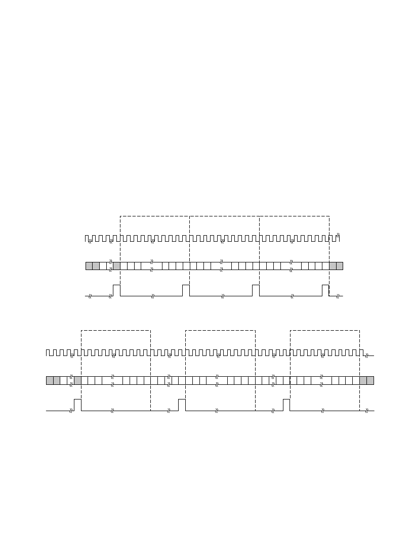
T he SDFS pin is used for the serial interface frame synchronization. New frames are marked by a one SCLK duration HI pulse,
driven out on SDFS, one serial clock period before the frame begins. Upon initializing, there are exactly 12 time slots per frame and
16 bits per time slot. T he frame rate is 57,291 and 2/3 Hz (11 MHz SCLK /(16 bits
×
12 slots)). T he frame rate can also be changed
from the default value by reprogramming the rate in registers. T he frame rate can run at the default rate or be programmed to match
the modem sample rate, ADC capture rate, DAC playback rate, music sample rate, I
2
S(1) sample rate or I
2
S(0) sample rate. When
the frame rate is not equivalent to the sample rate, Valid Out, Request In and Valid In bits are used to control the sample data flow.
When the frame rate is equivalent to the sample rate, Valid and Request bits can be ignored.
PDN
SCLK
SDI OR SDO
SDFS
15 14 13
0
1
2
3
SAMPLE PERIOD N
SLOT 0
SLOT 15
SLOT 0
SLOT 15
SLOT 0
SLOT 15
SAMPLE PERIOD N + 1
SAMPLE PERIOD N + 2
15 14 13
0
1
2
3
15 14 13
0
1
2
3
Figure 12. DSP Serial Interface (Default Frame Rate)
15 14 13
0
1
2
3
15 14 13
0
1
2
3
15 14 13
0
1
2
3
SCLK
SDI OR
SDO
SDFS
SAMPLE PERIOD N
SLOT 0
SLOT 15
SLOT 0
SLOT 15
SLOT 0
SLOT 15
SAMPLE PERIOD N + 1
SAMPLE PERIOD N + 2
Figure 13. DSP Serial Interface (User Programmed Frame Rate)
相關(guān)PDF資料 |
PDF描述 |
|---|---|
| AD1816AJST | SoundPort Controller |
| AD1816A | SoundPort Controller(數(shù)字音頻的聲音端口控制器) |
| AD1818 | PCI SoundComm DC97 Digital Controller(PCI SoundComm DC97型數(shù)字控制器) |
| AD1819A | AC97 SoundPort Codec(AC97型聲音端口信號編解碼器) |
| AD1819BJST | AC’97 SoundPort Codec |
相關(guān)代理商/技術(shù)參數(shù) |
參數(shù)描述 |
|---|---|
| ad1816ajs-eeprom | 制造商:Rochester Electronics LLC 功能描述:AD1816A SOUND PORT CONTRO - Bulk 制造商:Analog Devices 功能描述: |
| AD1816AJST | 制造商:AD 制造商全稱:Analog Devices 功能描述:SoundPort Controller |
| ad1816js3 | 制造商:Rochester Electronics LLC 功能描述:- Bulk 制造商:Analog Devices 功能描述: |
| AD18-182 | 制造商:Thomas & Betts 功能描述:Terminal; 22 to 18 AWG; Brass; Non-Insulated; Tin Plated; UL 94V-2 制造商:Thomas & Betts 功能描述:DISCONNECTFEMALE 制造商:Thomas & Betts 功能描述:Quick Disconnect Terminal 18-22AWG F 21.08mm 5.84mm Tin |
| AD18-183 | 制造商:Thomas & Betts 功能描述:Terminal; 22 to 18 AWG; Brass; Nylon; Tin Plated; UL 94V-2 制造商:Thomas & Betts 功能描述:NON-INS FEM-187 DISC, 22-18 LEN .64 制造商:Thomas & Betts 功能描述:Quick Disconnect Terminal 18-22AWG F 16.26mm 5.84mm Tin |
發(fā)布緊急采購,3分鐘左右您將得到回復。