- 您現(xiàn)在的位置:買(mǎi)賣(mài)IC網(wǎng) > PDF目錄378210 > 80546KF (Intel Corp.) 64-bit Intel Xeon Processor MP with up to 8MB L3 Cache PDF資料下載
參數(shù)資料
| 型號(hào): | 80546KF |
| 廠商: | Intel Corp. |
| 英文描述: | 64-bit Intel Xeon Processor MP with up to 8MB L3 Cache |
| 中文描述: | 64位Intel Xeon處理器MP的高達(dá)8MB三級(jí)高速緩存 |
| 文件頁(yè)數(shù): | 40/138頁(yè) |
| 文件大?。?/td> | 2666K |
| 代理商: | 80546KF |
第1頁(yè)第2頁(yè)第3頁(yè)第4頁(yè)第5頁(yè)第6頁(yè)第7頁(yè)第8頁(yè)第9頁(yè)第10頁(yè)第11頁(yè)第12頁(yè)第13頁(yè)第14頁(yè)第15頁(yè)第16頁(yè)第17頁(yè)第18頁(yè)第19頁(yè)第20頁(yè)第21頁(yè)第22頁(yè)第23頁(yè)第24頁(yè)第25頁(yè)第26頁(yè)第27頁(yè)第28頁(yè)第29頁(yè)第30頁(yè)第31頁(yè)第32頁(yè)第33頁(yè)第34頁(yè)第35頁(yè)第36頁(yè)第37頁(yè)第38頁(yè)第39頁(yè)當(dāng)前第40頁(yè)第41頁(yè)第42頁(yè)第43頁(yè)第44頁(yè)第45頁(yè)第46頁(yè)第47頁(yè)第48頁(yè)第49頁(yè)第50頁(yè)第51頁(yè)第52頁(yè)第53頁(yè)第54頁(yè)第55頁(yè)第56頁(yè)第57頁(yè)第58頁(yè)第59頁(yè)第60頁(yè)第61頁(yè)第62頁(yè)第63頁(yè)第64頁(yè)第65頁(yè)第66頁(yè)第67頁(yè)第68頁(yè)第69頁(yè)第70頁(yè)第71頁(yè)第72頁(yè)第73頁(yè)第74頁(yè)第75頁(yè)第76頁(yè)第77頁(yè)第78頁(yè)第79頁(yè)第80頁(yè)第81頁(yè)第82頁(yè)第83頁(yè)第84頁(yè)第85頁(yè)第86頁(yè)第87頁(yè)第88頁(yè)第89頁(yè)第90頁(yè)第91頁(yè)第92頁(yè)第93頁(yè)第94頁(yè)第95頁(yè)第96頁(yè)第97頁(yè)第98頁(yè)第99頁(yè)第100頁(yè)第101頁(yè)第102頁(yè)第103頁(yè)第104頁(yè)第105頁(yè)第106頁(yè)第107頁(yè)第108頁(yè)第109頁(yè)第110頁(yè)第111頁(yè)第112頁(yè)第113頁(yè)第114頁(yè)第115頁(yè)第116頁(yè)第117頁(yè)第118頁(yè)第119頁(yè)第120頁(yè)第121頁(yè)第122頁(yè)第123頁(yè)第124頁(yè)第125頁(yè)第126頁(yè)第127頁(yè)第128頁(yè)第129頁(yè)第130頁(yè)第131頁(yè)第132頁(yè)第133頁(yè)第134頁(yè)第135頁(yè)第136頁(yè)第137頁(yè)第138頁(yè)
40
64-bit Intel
Xeon Processor MP with up to 8MB L3 Cache Datasheet
Electrical Specifications
NOTES:
1. All AC timings for the GTL+ asynchronous signals are referenced to the BCLK0 rising edge at Crossing
Voltage (V
). All GTL+ asynchronous signal timings are referenced at GTLREF. PWRGOOD is
referenced to the BCLK0 rising edge at 0.5 * V
TT
.
2. These signals may be driven asynchronously.
3. Refer to the PWRGOOD definition for more details regarding the behavior of the signal.
4. Length of assertion for PROCHOT# does not equal TCC activation time. Time is required after the assertion
or deassertion of PROCHOT# for the processor to enable or disable the TCC. Additionally, time is allocated
after the assertion or deassertion of PROCHOT# for the processor to complete current instruction execution.
This specification applies to the PROCHOT# signal when asserted by the processor and the FORCEPR#
signal when asserted by the system.
5. Refer to
Section 8.2
for additional timing requirements for entering and leaving low power states.
6. Intel recommends the V
power supply also be removed upon assertion of THERMTRIP#.
7. A minimum pulse width of 500us is recommended when FORCEPR# is asserted by the system.
NOTES:
1. Before the clock that de-asserts RESET#
2. After the clock that de-asserts RESET#.
NOTES:
1. Not 100% tested. These parameters are based on design characterization.
2. This specification is based on the capabilities of the ITP-XDP debug port tool, not on processor silicon.
3. Referenced to the rising edge of TCK.
4. Referenced to the falling edge of TCK.
5. TRST# must be held asserted for 2 TCK periods to be guaranteed that it is recognized by the processor.
T38: PROCHOT#, FORCEPR# pulse width
500
μs
2-14
4
T39: THERMTRIP# assertion until V
CC
and
V
CACHE
removal
500
ms
2-15
6
T40: FERR# valid delay from STPCLK#
deassertion
0
5
BCLKs
2-20
T41: V
CC
to PWRGOOD assertion time
1
500
ms
2-18
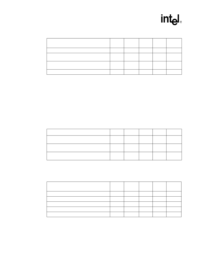
Table 2-23. Miscellaneous Signals AC Specifications (Sheet 2 of 2)
T# Parameter
Min
Max
Unit
Figure
Notes
1,2,5
Table 2-24. Front Side Bus AC Specifications (Reset Conditions)
T# Parameter
Min
Max
Unit
Figure
Notes
T47: Reset Configuration Signals (A[21:16]#)
Setup Time
1
ms
1
T45: Reset Configuration Signals (A[39:22]#,
A[15:3]#, BR[3:0]#, INIT#, SMI#) Setup Time
4
BCLKs
2-18
1
T46: Reset Configuration Signals (A[39:3]#,
BR[3:0]#, INIT#, SMI#) Hold Time
2
28
BCLKs
2-18
2
Table 2-25. TAP Signal Group AC Specifications
T# Parameter
Min
Max
Unit
Figure
Notes
1,7
T55: TCK Period
13.3
ns
2-7
2
T61: TDI, TMS Setup Time
1.5
ns
2-13
3,6
T62: TDI, TMS Hold Time
3.0
ns
2-13
3,6
T63: TDO Clock to Output Delay
0.5
10.0
ns
2-13
4
T64: TRST# Assert Time
2
TCK
2-14
5
相關(guān)PDF資料 |
PDF描述 |
|---|---|
| 8085AH | 8 BIT HMOS MICROPROCESSORS |
| 8085AH-1 | 8 BIT HMOS MICROPROCESSORS |
| 8085AH-2 | 8 BIT HMOS MICROPROCESSORS |
| 8087 | MATH COPROCESSOR |
| 8087-1 | Circular Connector; MIL SPEC:MIL-DTL-38999 Series III; Body Material:Metal; Series:TV06; No. of Contacts:61; Connector Shell Size:25; Connecting Termination:Crimp; Circular Shell Style:Straight Plug; Body Style:Straight |
相關(guān)代理商/技術(shù)參數(shù) |
參數(shù)描述 |
|---|---|
| 80546KG3200FA | 制造商:undefined 功能描述: |
| 805470 | 制造商:Phoenix Contact 功能描述:Labels Individual Label Polyester White 8x20mm |
| 80-5470-001 | 制造商:Applied Engineering Products (AEP) 功能描述:13"CBL W/CON ON BOTH ENDS - PLUG, R/A PUSHON - Bulk |
| 80547001 | 功能描述:MOTOR 82540 250RPM 220-230V 50/6 制造商:crouzet 系列:* 零件狀態(tài):在售 標(biāo)準(zhǔn)包裝:6 |
| 80547002 | 功能描述:MOTOR 82540 375RPM 220-230V 50HZ 制造商:crouzet 系列:* 零件狀態(tài):在售 標(biāo)準(zhǔn)包裝:6 |
發(fā)布緊急采購(gòu),3分鐘左右您將得到回復(fù)。