- 您現(xiàn)在的位置:買賣IC網(wǎng) > PDF目錄371415 > 272420-007 (Intel Corp.) Intel386 EX Embedded Microprocessor PDF資料下載
參數(shù)資料
| 型號: | 272420-007 |
| 廠商: | Intel Corp. |
| 英文描述: | Intel386 EX Embedded Microprocessor |
| 中文描述: | 英特爾386防爆嵌入式微處理器 |
| 文件頁數(shù): | 37/56頁 |
| 文件大小: | 766K |
| 代理商: | 272420-007 |
第1頁第2頁第3頁第4頁第5頁第6頁第7頁第8頁第9頁第10頁第11頁第12頁第13頁第14頁第15頁第16頁第17頁第18頁第19頁第20頁第21頁第22頁第23頁第24頁第25頁第26頁第27頁第28頁第29頁第30頁第31頁第32頁第33頁第34頁第35頁第36頁當(dāng)前第37頁第38頁第39頁第40頁第41頁第42頁第43頁第44頁第45頁第46頁第47頁第48頁第49頁第50頁第51頁第52頁第53頁第54頁第55頁第56頁
Intel386 EX Embedded Microprocessor
Datasheet
37
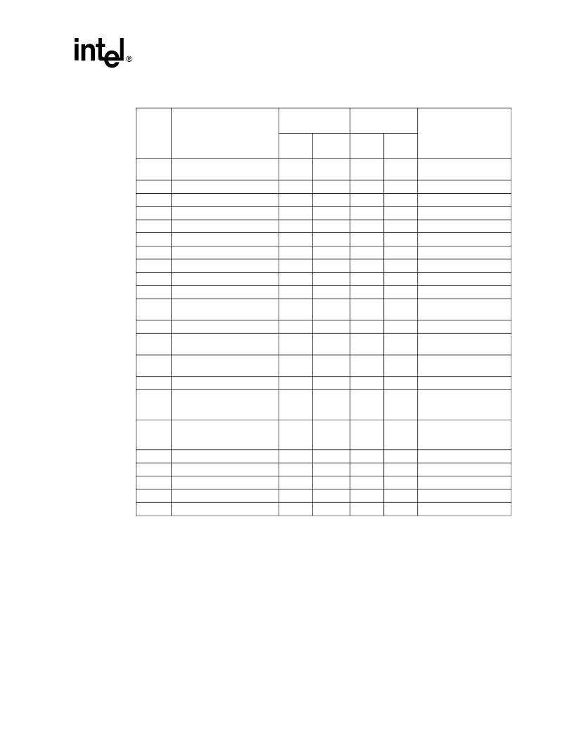
Table 12. 3-Volt AC Characteristics (Sheet 1 of 5)
Symbol
Parameter
25 MHz
3.0 V to 3.6 V
20 MHz
2.7 V to 3.6 V
Test Condition
Min.
(ns)
Max.
(ns)
Min.
(ns)
Max.
(ns)
Operating Frequency
0
25
0
20
one-half CLK2 frequency
in MHz
t
1
t
2a
t
2b
t
3a
t
3b
t
4
t
5
t
6
t
7
CLK2 Period
20
25
CLK2 High Time
7
8
(2)
CLK2 High Time
4
5
(2)
CLK2 Low Time
7
8
(2)
CLK2 Low Time
5
6
(2)
CLK2 Fall Time
7
8
(2)
CLK2 Rise Time
7
8
(2)
A25:1 Valid Delay
4
32
4
36
C
L
= 50 pF
(3)
A25:1 Float Delay
4
29
4
36
t
8
BHE#, BLE#, LOCK# Valid
Delay
4
32
4
34
C
L
= 50 pF
t
8a
SMIACT# Valid Delay
4
32
4
34
C
L
= 50 pF
t
9
BHE#, BLE#, LOCK# Float
Delay
4
23
4
32
(3)
t
10
M/IO#, D/C#, W/R#, ADS#,
REFRESH# Valid Delay
4
32
4
34
C
L
= 50 pF
t
10a
RD#, WR# Valid Delay
4
30
4
32
t
10b
WR# Valid Delay for the rising
edge with respect to phase
two (external late READY#)
4
37
4
37
(6)
t
11
M/IO#, D/C#, W/R#,
REFRESH#, ADS# Float
Delay
4
30
4
34
(3)
t
12
t
13
t
14
t
15
t
16
D15:0 Write Data Valid Delay
4
31
4
34
C
L
= 50 pF
(3)
D15:0 Write Data Float delay
4
20
4
28
HLDA Valid Delay
4
30
4
32
C
L
= 50 pF
NA# Setup Time
9
9
NA# Hold Time
12
15
NOTE:
1. Tested at maximum operating frequency and guaranteed by design characterization at lower operating
frequencies.
2. These are not tested. They are guaranteed by characterization.
3. Float condition occurs when maximum output current becomes less than I
LO
in magnitude. Float delay is not
fully tested.
4. These inputs may be asynchronous to CLK2. The setup and hold specifications are given to ensure
recognition within a specific CLK2 period.
5. These specifications are for information only and are not tested. They are intended to assist the designer in
selecting memory speeds. For each wait state in the design add two CLK2 cycles to the specification.
6. This specification assumes that READY# goes active after the rising edge of phase 2, so that WR# goes
inactive as a result of READY# falling.
7. This specification assumes that READY# goes active before the rising edge of phase 2, so that WR# goes
inactive as a result of phase 2 rising.
8. This specification applies if READY# is generated internally.
相關(guān)PDF資料 |
PDF描述 |
|---|---|
| 2729-170 | 170 Watts, 38 Volts, 100祍, 10% Radar 2700-2900 MHz |
| 2731-100M | 100 Watts, 36 Volts, 200us, 10% Radar 2700-3100 MHz |
| 2732 | MOS Memory Products |
| 273F06PP481R | POLYPROPYLENE-FOIL SELF CASED AXIAL LEADS |
| 273K06PP580R | POLYPROPYLENE-FOIL SELF CASED AXIAL LEADS |
相關(guān)代理商/技術(shù)參數(shù) |
參數(shù)描述 |
|---|---|
| 2724229 | 制造商:Phoenix Contact 功能描述:IBS ELR COV P-6A |
| 272423-000 | 功能描述:焊料和屏蔽管 CWT-9 RoHS:否 制造商:TE Connectivity / Raychem 類型:Shield Terminators 材料:Polyvinylidene Fluoride 內(nèi)徑:5.08 mm 長度:16.5 mm 最低收縮溫度: 系列:S03 |
| 2724232 | 制造商:Phoenix Contact 功能描述:IBS ELR COV W-6A |
| 2724245 | 制造商:Phoenix Contact 功能描述:IBS ELR COV 2-6A |
| 272-425A | 制造商:LG Corporation 功能描述:KNOBVOL/EQ, CFX-425A US1, TW |
發(fā)布緊急采購,3分鐘左右您將得到回復(fù)。