- 您現(xiàn)在的位置:買賣IC網 > PDF目錄371415 > 272420-007 (Intel Corp.) Intel386 EX Embedded Microprocessor PDF資料下載
參數(shù)資料
| 型號: | 272420-007 |
| 廠商: | Intel Corp. |
| 英文描述: | Intel386 EX Embedded Microprocessor |
| 中文描述: | 英特爾386防爆嵌入式微處理器 |
| 文件頁數(shù): | 16/56頁 |
| 文件大小: | 766K |
| 代理商: | 272420-007 |
第1頁第2頁第3頁第4頁第5頁第6頁第7頁第8頁第9頁第10頁第11頁第12頁第13頁第14頁第15頁當前第16頁第17頁第18頁第19頁第20頁第21頁第22頁第23頁第24頁第25頁第26頁第27頁第28頁第29頁第30頁第31頁第32頁第33頁第34頁第35頁第36頁第37頁第38頁第39頁第40頁第41頁第42頁第43頁第44頁第45頁第46頁第47頁第48頁第49頁第50頁第51頁第52頁第53頁第54頁第55頁第56頁
Intel386 EX Embedded Microprocessor
16
Datasheet
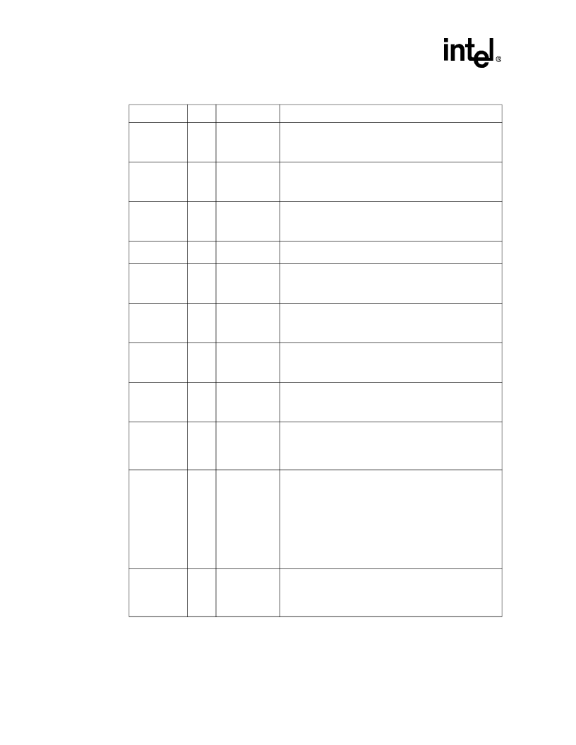
PWRDOWN
O
H(Q)
R(WL)
I(X)
P(1)
Powerdown
indicates that the processor is in powerdown mode.
PWRDOWN is multiplexed with P3.6.
RD#
O
H(1)
R(1)
I(1)
P(1)
Read
Enable
indicates that the current bus cycle is a read cycle.
READY#
I/O
H(Z)
R(Z)
I(Z)
P(Z)
Ready
indicates that the current bus transaction has completed.
An external device or an internal signal can drive READY#.
Internally, the chip-select wait-state logic can generate the ready
signal and drive the READY# pin active.
RESET
ST
Reset
suspends any operation in progress and places the
processor into a known reset state.
REFRESH#
O
H(1)
R(1)
I(Q)
P(X)
Refresh
indicates that the current bus cycle is a refresh cycle.
REFRESH# is multiplexed with CS6#.
RI1:0#
I
Ring Indicator SIO1 and SIO0
indicate that the modem or data
set has received a telephone ringing signal. RI1# is multiplexed
with SSIORX, and RI0# is multiplexed with P1.4 and has a
temporary weak pull-up resistor.
RTS1#
O
H(X)
R(WL)
I(X)
P(X)
Request-to-send SIO1 and SIO0
indicate that corresponding
asynchronous serial channel is ready to exchange data with the
modem or data set. RTS1# is multiplexed with SSIOTX, and
RTS0# is multiplexed with P1.1.
RTS0#
O
H(X)
R(WH)
I(X)
P(X)
Request-to-send SIO1 and SIO0
indicate that corresponding
asynchronous serial channel is ready to exchange data with the
modem or data set. RTS1# is multiplexed with SSIOTX, and
RTS0# is multiplexed with P1.1.
RXD1:0
I
Receive Data SIO1 and SIO0
accept serial data from the
modem or data set to the corresponding asynchronous serial
channel. RXD1 is multiplexed with DRQ1, and RXD0 is
multiplexed with P2.5 and has a temporary weak pull-down
resistor.
SMI#
ST
System Management Interrupt
invokes System Management
Mode (SMM). SMI# is the highest priority external interrupt. It is
latched on its falling edge and forces the CPU into SMM upon
completion of the current instruction. SMI# is recognized on an
instruction boundary and at each iteration for repeat string
instructions. SMI# cannot interrupt LOCKed bus cycles or a
currently executing SMM. When the processor receives a
second SMI# while in SMM, it latches the second SMI# on the
SMI# falling edge. However, the processor must exit SMM by
executing a resume instruction (RSM) before it can service the
second SMI#. SMI# has a permanent weak pull-up resistor.
SMIACT#
O
H(1)
R(1)
I(X)
P(X)
System Management Interrupt Active
indicates that the
processor is operating in System Management Mode (SMM). It
is asserted when the processor initiates an SMM sequence and
remains asserted (LOW) until the processor executes the
resume instruction (RSM).
Table 4.
Intel386 EX Microprocessor Pin Descriptions (Sheet 4 of 6)
Symbol
Type
Output States
Name and Function
NOTES:
1. X if clock source is internal; Q if clock source is external
2. Q if JTAG unit is shifting out data, Z if it is not
相關PDF資料 |
PDF描述 |
|---|---|
| 2729-170 | 170 Watts, 38 Volts, 100祍, 10% Radar 2700-2900 MHz |
| 2731-100M | 100 Watts, 36 Volts, 200us, 10% Radar 2700-3100 MHz |
| 2732 | MOS Memory Products |
| 273F06PP481R | POLYPROPYLENE-FOIL SELF CASED AXIAL LEADS |
| 273K06PP580R | POLYPROPYLENE-FOIL SELF CASED AXIAL LEADS |
相關代理商/技術參數(shù) |
參數(shù)描述 |
|---|---|
| 2724229 | 制造商:Phoenix Contact 功能描述:IBS ELR COV P-6A |
| 272423-000 | 功能描述:焊料和屏蔽管 CWT-9 RoHS:否 制造商:TE Connectivity / Raychem 類型:Shield Terminators 材料:Polyvinylidene Fluoride 內徑:5.08 mm 長度:16.5 mm 最低收縮溫度: 系列:S03 |
| 2724232 | 制造商:Phoenix Contact 功能描述:IBS ELR COV W-6A |
| 2724245 | 制造商:Phoenix Contact 功能描述:IBS ELR COV 2-6A |
| 272-425A | 制造商:LG Corporation 功能描述:KNOBVOL/EQ, CFX-425A US1, TW |
發(fā)布緊急采購,3分鐘左右您將得到回復。