- 您現(xiàn)在的位置:買賣IC網(wǎng) > PDF目錄372114 > SAA7146AH (NXP SEMICONDUCTORS) .012UF/400VDC METAL POLY CAP PDF資料下載
參數(shù)資料
| 型號(hào): | SAA7146AH |
| 廠商: | NXP SEMICONDUCTORS |
| 元件分類: | 消費(fèi)家電 |
| 英文描述: | .012UF/400VDC METAL POLY CAP |
| 中文描述: | SPECIALTY CONSUMER CIRCUIT, PQFP160 |
| 封裝: | 28 X 28 MM, 3.40 MM HEIGHT, PLASTIC, SOT322-2, MS-022, QFP-160 |
| 文件頁(yè)數(shù): | 75/144頁(yè) |
| 文件大小: | 645K |
| 代理商: | SAA7146AH |
第1頁(yè)第2頁(yè)第3頁(yè)第4頁(yè)第5頁(yè)第6頁(yè)第7頁(yè)第8頁(yè)第9頁(yè)第10頁(yè)第11頁(yè)第12頁(yè)第13頁(yè)第14頁(yè)第15頁(yè)第16頁(yè)第17頁(yè)第18頁(yè)第19頁(yè)第20頁(yè)第21頁(yè)第22頁(yè)第23頁(yè)第24頁(yè)第25頁(yè)第26頁(yè)第27頁(yè)第28頁(yè)第29頁(yè)第30頁(yè)第31頁(yè)第32頁(yè)第33頁(yè)第34頁(yè)第35頁(yè)第36頁(yè)第37頁(yè)第38頁(yè)第39頁(yè)第40頁(yè)第41頁(yè)第42頁(yè)第43頁(yè)第44頁(yè)第45頁(yè)第46頁(yè)第47頁(yè)第48頁(yè)第49頁(yè)第50頁(yè)第51頁(yè)第52頁(yè)第53頁(yè)第54頁(yè)第55頁(yè)第56頁(yè)第57頁(yè)第58頁(yè)第59頁(yè)第60頁(yè)第61頁(yè)第62頁(yè)第63頁(yè)第64頁(yè)第65頁(yè)第66頁(yè)第67頁(yè)第68頁(yè)第69頁(yè)第70頁(yè)第71頁(yè)第72頁(yè)第73頁(yè)第74頁(yè)當(dāng)前第75頁(yè)第76頁(yè)第77頁(yè)第78頁(yè)第79頁(yè)第80頁(yè)第81頁(yè)第82頁(yè)第83頁(yè)第84頁(yè)第85頁(yè)第86頁(yè)第87頁(yè)第88頁(yè)第89頁(yè)第90頁(yè)第91頁(yè)第92頁(yè)第93頁(yè)第94頁(yè)第95頁(yè)第96頁(yè)第97頁(yè)第98頁(yè)第99頁(yè)第100頁(yè)第101頁(yè)第102頁(yè)第103頁(yè)第104頁(yè)第105頁(yè)第106頁(yè)第107頁(yè)第108頁(yè)第109頁(yè)第110頁(yè)第111頁(yè)第112頁(yè)第113頁(yè)第114頁(yè)第115頁(yè)第116頁(yè)第117頁(yè)第118頁(yè)第119頁(yè)第120頁(yè)第121頁(yè)第122頁(yè)第123頁(yè)第124頁(yè)第125頁(yè)第126頁(yè)第127頁(yè)第128頁(yè)第129頁(yè)第130頁(yè)第131頁(yè)第132頁(yè)第133頁(yè)第134頁(yè)第135頁(yè)第136頁(yè)第137頁(yè)第138頁(yè)第139頁(yè)第140頁(yè)第141頁(yè)第142頁(yè)第143頁(yè)第144頁(yè)
1998 Apr 09
75
Philips Semiconductors
Product specification
Multimedia bridge, high performance
Scaler and PCI circuit (SPCI)
SAA7146A
1
17
to
1
18
(964)
16
1111 1111 1 1 1111 1111
2212 2212 2 2 2122 2122
1222 2222 1 1 2222 2221
...
1111 2222 1111
1111 2222 1111
1121 1212 1121
1211 2121 1211
FF, 00
44, BB
01, FE
...
0F, F0
18
32
32
...
32
3
4
4
...
4
16
18
1
1
...
1
...
...
22
1
23
to
1
24
(980)
AD, 52
32
4
1
VERTICAL
SCALE
RATIO
YACL
COEFFICIENT
SEQUENCE (EXAMPLE)
CYA; CYB
WEIGHT
SUM
DCGY
BCS
(CONTR. | SAT.)
= X/Y
×
64
7.9.2.6
LPI mode (scaling factor range 1 to
1
2
; register
bit YACM = 0)
To preserve the signal quality for slight vertical
downscales (scaling factors 1 to
1
2
) Linear Phase
Interpolation (LPI) between consecutive lines is
implemented to generate geometrically correct vertical
output lines. Thus, the new geometric position between
lines N and N + 1 can be calculated.
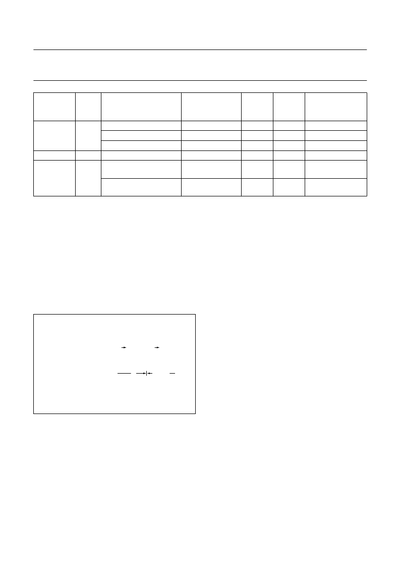
A new output line is calculated by weighting the samples
‘p’ of lines N and N + 1 with the normalized distance to the
newly calculated position:
p(M) = A
×
p(N + 1) + (1
A)
×
p(N); where A = 0 to
63
64
.
With N
OL
= Number of Output Lines and N
IL
= Number of
Input Lines the scaler register bits YSCI (scaling
increment) and YP (scaling start phase) have to be set
according to the following equations:
YSCI = INT [1024
×
(N
IL
/(N
OL
1)] scaling increment
YPx = INT [
YSCI
16
] scaling start phase (recommended
value).
Fig.22 Calculation of output lines.
handbook, halfpage
MHB107
N Distance = 1 N
+
1
I
I
I
M
I
A
(1
A)
input lines
new calculated position line
of output line M
The vertical start phase offset is defined by
YP
64
(YP = 0 to 64):
YP = 0: offset = 0 geometrical position of 1st
line
out
= 1st line
in
YP = 64: offset =
64
64
= 1 geometrical position of
1st line
out
= 2nd line
in
.
Finally 3 special modes are to be emphasized:
1.
Bypass
(YSCI = 0, YP = 64); each line
out
is equivalent
to corresponding line
in
2.
Low-pass
(YSCI = 0, YP < 64); e.g. YP = 32: average
value of 2 lines (1 + z
h
filter)
3.
For processing of
interlaced input
signals the LPI
mode must be used (ACCU mode would cause ‘line
pairing’ problems). The scaling start phase for odd and
even field have to be set to:
YP
even
=
3
2
×
YP
odd
(line 1 = odd)
In modes 1 and 2 the first input line is fed to the output
(without processing), so that the number of output lines
equals the number of input lines
7.9.2.7
Flip option (Mirror = 1)
For both vertical scaling modes there is a flip option
‘mirroring’ available for input lines with a maximum of
384 pixels. In the case of full screen pictures (e.g.
768
×
576) that have to be flipped, they first have to be
downscaled to 384 pixel/line in the horizontal prescaling
unit and after vertical processing (flipping) they may be
rezoomed to the original 768 pixels/line in the following
VPD.
It should be noted that, when using the flip option, the last
input line can not be displayed at the output.
相關(guān)PDF資料 |
PDF描述 |
|---|---|
| SAA7146A | Multimedia bridge, high performance Scaler and PCI circuit SPCI |
| SAA7151 | Digital multistandard colour decoder with SCART interface DMSD2-SCART |
| SAA7151B | Digital multistandard colour decoder with SCART interface DMSD2-SCART |
| SAA7157 | Clock signal generator circuit for digital TV systems SCGC |
| SAA7157T | Clock signal generator circuit for digital TV systems SCGC |
相關(guān)代理商/技術(shù)參數(shù) |
參數(shù)描述 |
|---|---|
| SAA7146AH/V3,557 | 制造商:NXP Semiconductors 功能描述: |
| SAA7146AH/V4,557 | 功能描述:視頻 IC VIDEO PCI BRIDGE (QFP160) RoHS:否 制造商:Fairchild Semiconductor 工作電源電壓:5 V 電源電流:80 mA 最大工作溫度:+ 85 C 封裝 / 箱體:TSSOP-28 封裝:Reel |
| SAA7146AH-V4.557 | 制造商:PHILIPS 制造商全稱:NXP Semiconductors 功能描述:Multimedia bridge, high performance Scaler and PCI circuit |
| SAA7146AHZ | 制造商:PHILIPS 制造商全稱:NXP Semiconductors 功能描述:Multimedia bridge, high performance Scaler and PCI circuit SPCI |
| SAA7151 | 制造商:PHILIPS 制造商全稱:NXP Semiconductors 功能描述:Digital multistandard colour decoder with SCART interface DMSD2-SCART |
發(fā)布緊急采購(gòu),3分鐘左右您將得到回復(fù)。