- 您現(xiàn)在的位置:買賣IC網(wǎng) > PDF目錄369944 > P89C738 (NXP Semiconductors N.V.) 8-bit Flash microcontrollers PDF資料下載
參數(shù)資料
| 型號(hào): | P89C738 |
| 廠商: | NXP Semiconductors N.V. |
| 英文描述: | 8-bit Flash microcontrollers |
| 中文描述: | 8位閃存微控制器 |
| 文件頁數(shù): | 24/64頁 |
| 文件大?。?/td> | 360K |
| 代理商: | P89C738 |
第1頁第2頁第3頁第4頁第5頁第6頁第7頁第8頁第9頁第10頁第11頁第12頁第13頁第14頁第15頁第16頁第17頁第18頁第19頁第20頁第21頁第22頁第23頁當(dāng)前第24頁第25頁第26頁第27頁第28頁第29頁第30頁第31頁第32頁第33頁第34頁第35頁第36頁第37頁第38頁第39頁第40頁第41頁第42頁第43頁第44頁第45頁第46頁第47頁第48頁第49頁第50頁第51頁第52頁第53頁第54頁第55頁第56頁第57頁第58頁第59頁第60頁第61頁第62頁第63頁第64頁

1998 Apr 07
24
Philips Semiconductors
Product specification
8-bit Flash microcontrollers
P89C738; P89C739
10.3
Watchdog Timer (T3)
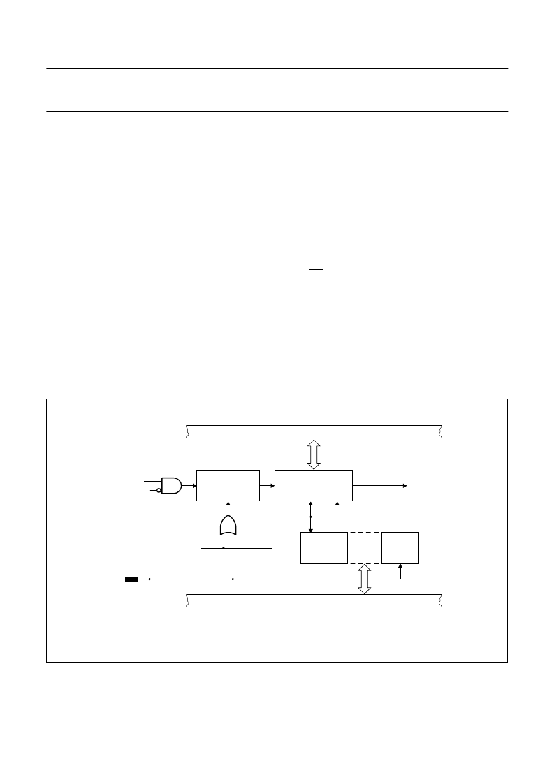
The Watchdog Timer (see Fig.14), consists of an 11-bit
prescaler and an 8-bit timer formed by SFR T3. The timer
is incremented every 1.5 ms, which is derived from the
system clock frequency of 16 MHz by the following
f
2048
×
)
formula:
The 8-bit timer increments every 12
×
2048 cycles of the
on-chip oscillator. When a timer overflow occurs, the
microcontroller is reset. The internal reset signal is not
inhibited when the external RST pin is kept LOW, e.g. by
an external reset circuit. The reset signal drives Ports 1, 2,
3, 4 and 5 outputs into the HIGH state and Port 0 into
high-impedance, no matter whether the clock oscillator is
running or not.
To prevent a system reset the timer must be reloaded in
time by the application software. If the processor suffers a
hardware/software malfunction, the software will fail to
reload the timer. This failure will result in a reset upon
overflow thus preventing the processor running out of
control.
f
timer
--12
=
This time interval is determined by the 8-bit reload value
that is written into register T3:
--T3
=
The Watchdog Timer can only be reloaded if the condition
flag WLE (PCON.4) has been previously set HIGH by
software. At the moment the counter is loaded WLE is
automatically cleared.
In the Idle mode the Watchdog Timer and reset circuitry
remain active.
The Watchdog Timer is controlled by the Watchdog enable
signal EW (EBTCON.1). A HIGH level enables the
Watchdog Timer and disables the Power-down mode.
A LOW level disables the Watchdog Timer and enables
the Power-down mode.
Watchdog time interval
]
12
f
clk
×
2048
×
Fig.14 Watchdog Timer block diagram.
handbook, full pagewidth
MBH081
INTERNAL BUS
1/12 fclk
write
T3
PRESCALER
11-BIT
TIMER T3 (8-BIT)
LOAD
CLEAR
to reset circuitry
LOADEN
EW
LOADEN
PCON.4
PCON.1
CLEAR
WLE
PD
INTERNAL BUS
(1)
(1) See Fig.21.
相關(guān)PDF資料 |
PDF描述 |
|---|---|
| P89C739ABA | 8-bit Flash microcontrollers |
| P89C739ABB | 8-bit Flash microcontrollers |
| P89C738ABA | 8-bit Flash microcontrollers |
| P89C738ABB | 8-bit Flash microcontrollers |
| P89C738ABP | 8-bit Flash microcontrollers |
相關(guān)代理商/技術(shù)參數(shù) |
參數(shù)描述 |
|---|---|
| P89C738ABA | 制造商:PHILIPS 制造商全稱:NXP Semiconductors 功能描述:8-bit Flash microcontrollers |
| P89C738ABB | 制造商:PHILIPS 制造商全稱:NXP Semiconductors 功能描述:8-bit Flash microcontrollers |
| P89C738ABP | 制造商:PHILIPS 制造商全稱:NXP Semiconductors 功能描述:8-bit Flash microcontrollers |
| P89C738BBB | 制造商:未知廠家 制造商全稱:未知廠家 功能描述:8-Bit Microcontroller |
| P89C739 | 制造商:PHILIPS 制造商全稱:NXP Semiconductors 功能描述:8-bit Flash microcontrollers |
發(fā)布緊急采購,3分鐘左右您將得到回復(fù)。