- 您現(xiàn)在的位置:買賣IC網(wǎng) > PDF目錄362685 > EM78569 (ELAN Microelctronics Corp .) 8-BIT MICRO-CONTROLLER PDF資料下載
參數(shù)資料
| 型號(hào): | EM78569 |
| 廠商: | ELAN Microelctronics Corp . |
| 英文描述: | 8-BIT MICRO-CONTROLLER |
| 中文描述: | 8位微控制器 |
| 文件頁(yè)數(shù): | 42/53頁(yè) |
| 文件大?。?/td> | 461K |
| 代理商: | EM78569 |
第1頁(yè)第2頁(yè)第3頁(yè)第4頁(yè)第5頁(yè)第6頁(yè)第7頁(yè)第8頁(yè)第9頁(yè)第10頁(yè)第11頁(yè)第12頁(yè)第13頁(yè)第14頁(yè)第15頁(yè)第16頁(yè)第17頁(yè)第18頁(yè)第19頁(yè)第20頁(yè)第21頁(yè)第22頁(yè)第23頁(yè)第24頁(yè)第25頁(yè)第26頁(yè)第27頁(yè)第28頁(yè)第29頁(yè)第30頁(yè)第31頁(yè)第32頁(yè)第33頁(yè)第34頁(yè)第35頁(yè)第36頁(yè)第37頁(yè)第38頁(yè)第39頁(yè)第40頁(yè)第41頁(yè)當(dāng)前第42頁(yè)第43頁(yè)第44頁(yè)第45頁(yè)第46頁(yè)第47頁(yè)第48頁(yè)第49頁(yè)第50頁(yè)第51頁(yè)第52頁(yè)第53頁(yè)
EM78569
8-bit Micro-controller
__________________________________________________________________________________________________________________________________________________________________
* This specification is subject to be changed without notice.
8/31/2004 (V4.0)
VII.5 RESET
The RESET can be caused by
(1) Power on reset
(2) WDT timeout. (if enabled and in GREEN or NORMAL mode)
(3) /RESET pin pull low
Once the RESET occurs, the following functions are performed.
The oscillator is running, or will be started.
The Program Counter (R2) is set to all "0".
When power on, the upper 3 bits of R3 and the upper 2 bits of R4 are cleared.
The Watchdog timer and prescaler counter are cleared.
The Watchdog timer is disabled.
The CONT register is set to all "1"
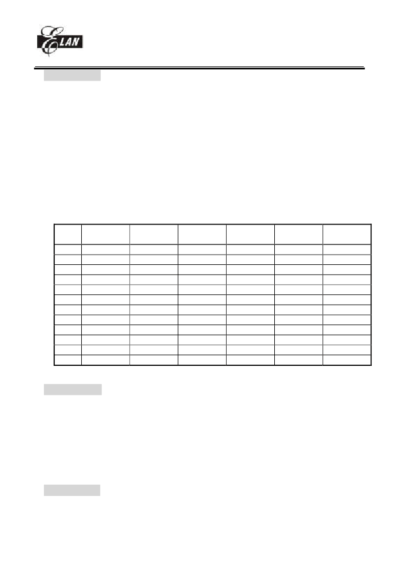
The other register (bit 7 ~ bit 0) default values are as follows.
Operation registers :
Address
R register
PAGE0
PAGE1
0x4
00xxxxxx
0x5
xxxx0000
xxxx0000
0x6
xxxxxxxx
xxxxxxxx
0x7
xxxxxxxx
xxxx0000
0x8
xxxxxxxx
00000000
0x9
xxxxxxxx
xxxxxxxx
0xA
00011xx0
11111111
0xB
xxxxxxxx
xxxxxxxx
0xC
xxxxxxxx
00000000
0xD
xxxxx000
00000000
0xE
00000000
0xF
00000000
R register
R register
PAGE2
00000000
xxxxxxxx
0x000000
xxxxxxxx
xxxxxxxx
xxxxxxxx
xxxxxxxx
R register
PAGE3
00000000
00000000
xxxxxx00
00000000
00000000
xxxxxx00
00000000
IOC register
PAGE0
111x0000
11111111
11111111
11111111
11111111
xxxxxxxx
11111111
11111111
xxxxxxxx
0000xxxx
00000000
IOC register
PAGE1
00000000
00000000
00000000
00000000
x0xx0xx
000000x0
00000000
00000000
xxxxxxxx
VII.6 Wake-up
The controller provided sleep mode for power saving :
SLEEP mode, RA(7) = 0 + "SLEP" instruction
The controller will turn off all the CPU and crystal. Other circuit with power control like key tone control or
PLL control (which has enable register), user has to turn it off by software.
Wake-up from SLEEP mode
(1) WDT time out
(2) External interrupt
(3) /RESET pull low
All these cases will reset controller , and run the program at address zero. The status just like the power on reset.
VII.7 Interrupt
RF is the interrupt status register which records the interrupt request in flag bit. IOCF is the interrupt mask
register. Global interrupt is enabled by ENI instruction and is disabled by DISI instruction. When one of the
相關(guān)PDF資料 |
PDF描述 |
|---|---|
| EM785830AA | 8-BIT MICRO-CONTROLLER |
| EM785830AAM | 8-BIT MICRO-CONTROLLER |
| EM785830AAP | 8-BIT MICRO-CONTROLLER |
| EM785830AD | 8-BIT MICRO-CONTROLLER |
| EM785830ADQ | 8-BIT MICRO-CONTROLLER |
相關(guān)代理商/技術(shù)參數(shù) |
參數(shù)描述 |
|---|---|
| EM785830AA | 制造商:EMC 制造商全稱:ELAN Microelectronics Corp 功能描述:8-BIT MICRO-CONTROLLER |
| EM785830AAM | 制造商:EMC 制造商全稱:ELAN Microelectronics Corp 功能描述:8-BIT MICRO-CONTROLLER |
| EM785830AAP | 制造商:EMC 制造商全稱:ELAN Microelectronics Corp 功能描述:8-BIT MICRO-CONTROLLER |
| EM785830AD | 制造商:EMC 制造商全稱:ELAN Microelectronics Corp 功能描述:8-BIT MICRO-CONTROLLER |
| EM785830ADQ | 制造商:EMC 制造商全稱:ELAN Microelectronics Corp 功能描述:8-BIT MICRO-CONTROLLER |
發(fā)布緊急采購(gòu),3分鐘左右您將得到回復(fù)。