- 您現(xiàn)在的位置:買賣IC網(wǎng) > PDF目錄171235 > DSRT-L030-011 (CONEXANT SYSTEMS) SPECIALTY CONSUMER CIRCUIT, XMA PDF資料下載
參數(shù)資料
| 型號(hào): | DSRT-L030-011 |
| 廠商: | CONEXANT SYSTEMS |
| 元件分類: | 消費(fèi)家電 |
| 英文描述: | SPECIALTY CONSUMER CIRCUIT, XMA |
| 文件頁(yè)數(shù): | 39/86頁(yè) |
| 文件大?。?/td> | 667K |
| 代理商: | DSRT-L030-011 |
第1頁(yè)第2頁(yè)第3頁(yè)第4頁(yè)第5頁(yè)第6頁(yè)第7頁(yè)第8頁(yè)第9頁(yè)第10頁(yè)第11頁(yè)第12頁(yè)第13頁(yè)第14頁(yè)第15頁(yè)第16頁(yè)第17頁(yè)第18頁(yè)第19頁(yè)第20頁(yè)第21頁(yè)第22頁(yè)第23頁(yè)第24頁(yè)第25頁(yè)第26頁(yè)第27頁(yè)第28頁(yè)第29頁(yè)第30頁(yè)第31頁(yè)第32頁(yè)第33頁(yè)第34頁(yè)第35頁(yè)第36頁(yè)第37頁(yè)第38頁(yè)當(dāng)前第39頁(yè)第40頁(yè)第41頁(yè)第42頁(yè)第43頁(yè)第44頁(yè)第45頁(yè)第46頁(yè)第47頁(yè)第48頁(yè)第49頁(yè)第50頁(yè)第51頁(yè)第52頁(yè)第53頁(yè)第54頁(yè)第55頁(yè)第56頁(yè)第57頁(yè)第58頁(yè)第59頁(yè)第60頁(yè)第61頁(yè)第62頁(yè)第63頁(yè)第64頁(yè)第65頁(yè)第66頁(yè)第67頁(yè)第68頁(yè)第69頁(yè)第70頁(yè)第71頁(yè)第72頁(yè)第73頁(yè)第74頁(yè)第75頁(yè)第76頁(yè)第77頁(yè)第78頁(yè)第79頁(yè)第80頁(yè)第81頁(yè)第82頁(yè)第83頁(yè)第84頁(yè)第85頁(yè)第86頁(yè)

RipTide PCI Audio/Comm Device Family Product Description
44
ROCKWELL PROPRIETARY INFORMATION
1167
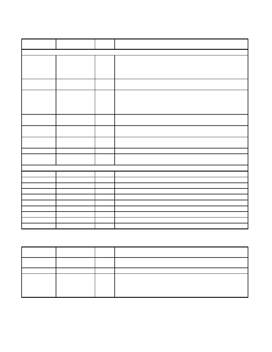
6.2.3
Controller Serial Bus Interface
Signal
Pin No.
I/O
Type
Interface
Controller to Modem DSP Serial Interface
RDCLK
50
O
Modem Serial Receive Clock. The frequency is the data rate (
± 0.01%) with a
duty cycle of 50
± 1%. The data rate is the rate of data transfer of the modem
connection, e.g., a 56 Kbps connection would result in a RDCLK frequency of 56
kHz. The RDCLK low-to-high transitions coincide with the center of the received
data bits. Internal pull-up. Connect to Controller: MRXCLK input.
M_RXD
3
O
Modem Serial Receive Data. Received serial data to Controller.
Connect to Controller: MRXD input.
TDCLK
54
O
Modem Serial Transmit Clock.. The frequency is the data rate (
± 0.01%) with
a duty cycle of 50
± 1%. The data rate is the rate of data transfer of the modem
connection, e.g., a 56 Kbps connection would result in a TDCLK frequency of 56
kHz. Internal pull-up.
Connect to Controller: MTXCLK input.
TXD
55
I
Modem Serial Transmit Clock. Transmit serial data from the Controller.
Connect to Controller: MTXD output.
SR4CLK
70
I
Voice Serial Bit Clock. Pad with repeater (keeper).
Connect to Controller: SR8CLK.
SA4CLK
69
I
Voice Serial Frame Clock. Pad with repeater (keeper).
Connect to Controller: SR8FRM.
SR8OUT
72
O
Voice Data Downstream. Connect to Controller: SR8DD.
SR8IN
71
I
Voice Data Upstream. Pad with repeater (keeper).
Connect to Controller: SR8DU.
Codec (via the Controller) to Modem DSP Serial Interface
IA1CLK
67
I
Codec Bit Clock. Connect to Controller SR1234CLK. Internal pull-up.
SA1CLK
66
I
Codec Frame Clock. Connect to Controller SR1234FRM. Internal pull-up.
SR1IO
78
O
Modem Codec Mode Control. Connect to Controller SR2IN.
SR4IN
79
I
Modem Serial Data Out. Connect to Controller SR4OUT. Internal keeper.
SR4OUT
63
O
Modem Serial Data In. Connect to Controller SR4IN.
SR2CLK
52
I
Codec Bit Clock. Connect to Controller SR1234CLK. Internal pull-up.
SA2CLK
75
I
Codec Frame Clock. Connect to Controller SR1234FRM. Internal pull-up.
SR2IO
76
O
Voice Codec Mode Control. Connect to Controller SR1IN.
SR3IN
65
I
Voice Serial Data Out. Connect to Controller SR3OUT.
SR3OUT
64
O
Voice Serial Data In. Connect to Controller SR3INT.
6.2.4
Miscellaneous
Signal
Pin No.
I/O
Type
Interface
MK4
21
I
MK4 PLL Circuit Disable/Enable Option. Connect to digital ground to operate
at 28.224 MHz clock input. When low, internal PLL in use.
MK5
61
Ipu
MK5 PLL Circuit Disable/Enable Option. Internal pull-up. Leave floating.
RESERVED or
other pins not
used
2, 5, 6, 7, 9, 10, 11,
13, 14, 15, 16, 17,
22, 23, 24, 34, 42,
53, 56, 58, 59, 60,
73, 74, 77, 80
Reserved Pins or Pins Not used. No external connection.
相關(guān)PDF資料 |
PDF描述 |
|---|---|
| DSRT-L050-011 | SPECIALTY CONSUMER CIRCUIT, XMA |
| DSS710D223S12-22 | 1 FUNCTIONS, 12 V, 7 A, DATA LINE FILTER |
| DST9HB32E101Q55J | 1 FUNCTIONS, 250 V, 6 A, DATA LINE FILTER |
| DST9HB32E220Q55J | 1 FUNCTIONS, 250 V, 6 A, DATA LINE FILTER |
| DST9HB32E222Q55J | 1 FUNCTIONS, 250 V, 6 A, DATA LINE FILTER |
相關(guān)代理商/技術(shù)參數(shù) |
參數(shù)描述 |
|---|---|
| DSR-TSS-S1 | 制造商:DOMINANT 制造商全稱:DOMINANT Semiconductors 功能描述:Right Angle LED |
| DSR-TSS-S2 | 制造商:DOMINANT 制造商全稱:DOMINANT Semiconductors 功能描述:Right Angle LED |
| DSR-TSS-ST2-1 | 制造商:DOMINANT 制造商全稱:DOMINANT Semiconductors 功能描述:Right Angle LED |
| DSR-TSS-T1 | 制造商:DOMINANT 制造商全稱:DOMINANT Semiconductors 功能描述:Right Angle LED |
| DSR-TSS-T2 | 制造商:DOMINANT 制造商全稱:DOMINANT Semiconductors 功能描述:Right Angle LED |
發(fā)布緊急采購(gòu),3分鐘左右您將得到回復(fù)。