- 您現(xiàn)在的位置:買賣IC網(wǎng) > PDF目錄378513 > CY7C60123 (Cypress Semiconductor Corp.) Wireless enCoRe II Microcontroller(無線enCoRe II微控制器) PDF資料下載
參數(shù)資料
| 型號(hào): | CY7C60123 |
| 廠商: | Cypress Semiconductor Corp. |
| 英文描述: | Wireless enCoRe II Microcontroller(無線enCoRe II微控制器) |
| 中文描述: | 的Wireless enCoRe II微控制器(無線enCoRe II還微控制器) |
| 文件頁數(shù): | 16/62頁 |
| 文件大?。?/td> | 1276K |
| 代理商: | CY7C60123 |
第1頁第2頁第3頁第4頁第5頁第6頁第7頁第8頁第9頁第10頁第11頁第12頁第13頁第14頁第15頁當(dāng)前第16頁第17頁第18頁第19頁第20頁第21頁第22頁第23頁第24頁第25頁第26頁第27頁第28頁第29頁第30頁第31頁第32頁第33頁第34頁第35頁第36頁第37頁第38頁第39頁第40頁第41頁第42頁第43頁第44頁第45頁第46頁第47頁第48頁第49頁第50頁第51頁第52頁第53頁第54頁第55頁第56頁第57頁第58頁第59頁第60頁第61頁第62頁
CY7C601xx
CY7C602xx
Document 38-16016 Rev. *C
Page 16 of 62
Two important variables that are used for all functions are
KEY1 and KEY2. These variables are used to help discrim-
inate between valid SSCs and inadvertent SSCs. KEY1 must
always have a value of 3Ah, while KEY2 must have the same
value as the stack pointer when the SROM function begins
execution. This would be the Stack Pointer value when the
SSC opcode is executed, plus three. If either of the keys do
not match the expected values, the M8C will halt (with the
exception of the SWBootReset function). The following code
puts the correct value in KEY1 and KEY2. The code starts with
a halt, to force the program to jump directly into the setup code
and not run into it.
halt
SSCOP: mov [KEY1], 3ah
mov X, SP
mov A, X
add A, 3
mov [KEY2], A
Return Codes
The SROM also features Return Codes and Lockouts.
Return codes aid in the determination of success or failure of
a particular function. The return code is stored in KEY1’s
position in the parameter block. The CheckSum and
TableRead functions do not have return codes because
KEY1’s position in the parameter block is used to return other
data.
Read, write, and erase operations may fail if the target block
is read or write protected. Block protection levels are set
during device programming.
The EraseAll function overwrites data in addition to leaving the
entire user Flash in the erase state. The EraseAll function
loops through the number of Flash macros in the product,
executing the following sequence: erase, bulk program all
zeros, erase. After all the user space in all the Flash macros
are erased, a second loop erases and then programs each
protection block with zeros.
SROM Function Descriptions
SWBootReset Function
The SROM function, SWBootReset, is the function that is
responsible for transitioning the device from a reset state to
running user code. The SWBootReset function is executed
whenever the SROM is entered with an M8C accumulator
value of 00h: the SRAM parameter block is not used as an
input to the function. This will happen, by design, after a
hardware reset, because the M8C's accumulator is reset to
00h or when user code executes the SSC instruction with an
accumulator value of 00h. The SWBootReset function will not
execute when the SSC instruction is executed with a bad key
value and a non-zero function code. An enCoRe II LV device
will execute the HALT instruction if a bad value is given for
either KEY1 or KEY2.
The SWBootReset function verifies the integrity of the
calibration data by way of a 16-bit checksum, before releasing
the M8C to run user code.
ReadBlock Function
The ReadBlock function is used to read 64 contiguous bytes
from Flash: a block.
The first thing this function does is to check the protection bits
and determine if the desired BLOCKID is readable. If read
protection is turned on, the ReadBlock function will exit setting
the accumulator and KEY2 back to 00h. KEY1 will have a
value of 01h, indicating a read failure. If read protection is not
enabled, the function will read 64 bytes from the Flash using
a ROMX instruction and store the results in SRAM using an
MVI instruction. The first of the 64 bytes will be stored in SRAM
at the address indicated by the value of the POINTER
parameter. When the ReadBlock completes successfully the
accumulator, KEY1 and KEY2 will all have a value of 00h.
WriteBlock Function
The WriteBlock function is used to store data in the Flash. Data
is moved 64 bytes at a time from SRAM to Flash using this
function. The first thing the WriteBlock function does is to
check the protection bits and determine if the desired
BLOCKID is writable. If write protection is turned on, the Write-
Block function will exit setting the accumulator and KEY2 back
to 00h. KEY1 will have a value of 01h, indicating a write failure.
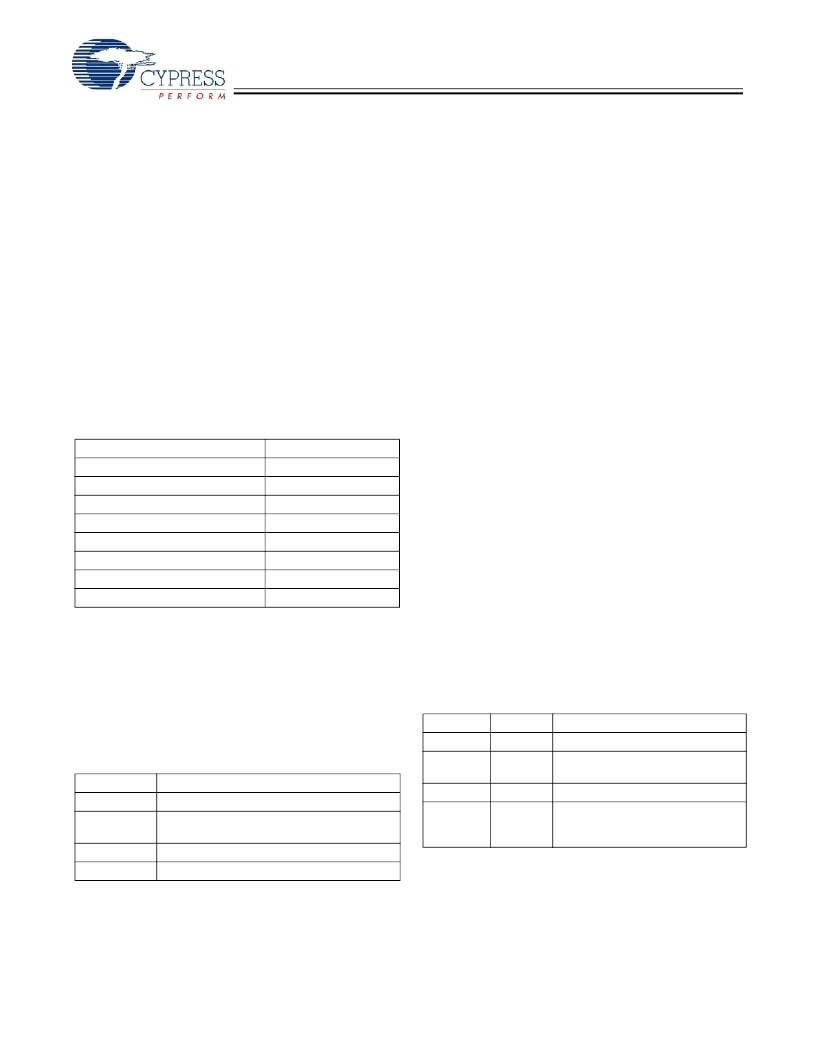
Table 21.SROM Function Parameters
Variable Name
SRAM Address
0,F8h
0,F9h
0,FAh
0,FBh
0,FCh
0,FDh
0,FEh
0,FFh
Key1/Counter/Return Code
Key2/TMP
BlockID
Pointer
Clock
Mode
Delay
PCL
Table 22.SROM Return Codes
Return Code
00h
01h
Description
Success
Function not allowed due to level of protection
on block
Software reset without hardware reset
Fatal error, SROM halted
02h
03h
Table 23.ReadBlock Parameters
Name
KEY1
KEY2
Address
0,F8h
0,F9h
Description
3Ah
Stack Pointer value, when SSC is
executed
Flash block number
First of 64 addresses in SRAM
where returned data should be
stored
BLOCKID
POINTER
0,FAh
0,FBh
相關(guān)PDF資料 |
PDF描述 |
|---|---|
| CY7C60223 | Wireless enCoRe II Microcontroller(無線enCoRe II微控制器) |
| CY7C60333 | enCoRe III Low Voltage(enCoRe III低電壓) |
| CY7C60323 | enCoRe III Low Voltage(enCoRe III低電壓) |
| CY7C63001C | Universal Serial Bus Microcontroller(通用串行總線微控制器) |
| CY7C63231-PC | enCoRe USB Low-speed USB Peripheral Controller |
相關(guān)代理商/技術(shù)參數(shù) |
參數(shù)描述 |
|---|---|
| CY7C60123-3X14C | 制造商:Cypress Semiconductor 功能描述:CY7C60123-3X14C - Bulk 制造商:Cypress Semiconductor 功能描述:USB |
| CY7C60123-3XWC | 制造商:Cypress Semiconductor 功能描述:USB - Bulk |
| CY7C60123-PVXC | 功能描述:8位微控制器 -MCU 8K Flash 256byte RAM 48 COM RoHS:否 制造商:Silicon Labs 核心:8051 處理器系列:C8051F39x 數(shù)據(jù)總線寬度:8 bit 最大時(shí)鐘頻率:50 MHz 程序存儲(chǔ)器大小:16 KB 數(shù)據(jù) RAM 大小:1 KB 片上 ADC:Yes 工作電源電壓:1.8 V to 3.6 V 工作溫度范圍:- 40 C to + 105 C 封裝 / 箱體:QFN-20 安裝風(fēng)格:SMD/SMT |
| CY7C60123-PVXCKJ | 制造商:Cypress Semiconductor 功能描述: |
| CY7C60123-PXC | 功能描述:8位微控制器 -MCU 8K Flash 256byte RAM 48 COM RoHS:否 制造商:Silicon Labs 核心:8051 處理器系列:C8051F39x 數(shù)據(jù)總線寬度:8 bit 最大時(shí)鐘頻率:50 MHz 程序存儲(chǔ)器大小:16 KB 數(shù)據(jù) RAM 大小:1 KB 片上 ADC:Yes 工作電源電壓:1.8 V to 3.6 V 工作溫度范圍:- 40 C to + 105 C 封裝 / 箱體:QFN-20 安裝風(fēng)格:SMD/SMT |
發(fā)布緊急采購,3分鐘左右您將得到回復(fù)。