- 您現(xiàn)在的位置:買(mǎi)賣(mài)IC網(wǎng) > PDF目錄379094 > CY7C43644 (Cypress Semiconductor Corp.) 1K x36 x2 Bidirectional Synchronous FIFO w/ Bus Matching(1K x36 x2 雙向同步先進(jìn)先出帶總線(xiàn)匹配) PDF資料下載
參數(shù)資料
| 型號(hào): | CY7C43644 |
| 廠(chǎng)商: | Cypress Semiconductor Corp. |
| 英文描述: | 1K x36 x2 Bidirectional Synchronous FIFO w/ Bus Matching(1K x36 x2 雙向同步先進(jìn)先出帶總線(xiàn)匹配) |
| 中文描述: | 每1000 x36 x2雙向同步FIFO瓦特/總線(xiàn)匹配(每1000 x36 x2雙向同步先進(jìn)先出帶總線(xiàn)匹配) |
| 文件頁(yè)數(shù): | 4/37頁(yè) |
| 文件大小: | 581K |
| 代理商: | CY7C43644 |
第1頁(yè)第2頁(yè)第3頁(yè)當(dāng)前第4頁(yè)第5頁(yè)第6頁(yè)第7頁(yè)第8頁(yè)第9頁(yè)第10頁(yè)第11頁(yè)第12頁(yè)第13頁(yè)第14頁(yè)第15頁(yè)第16頁(yè)第17頁(yè)第18頁(yè)第19頁(yè)第20頁(yè)第21頁(yè)第22頁(yè)第23頁(yè)第24頁(yè)第25頁(yè)第26頁(yè)第27頁(yè)第28頁(yè)第29頁(yè)第30頁(yè)第31頁(yè)第32頁(yè)第33頁(yè)第34頁(yè)第35頁(yè)第36頁(yè)第37頁(yè)
CY7C43624
CY7C43634/CY7C43644
CY7C43664/CY7C43684
4
PRELIMINARY
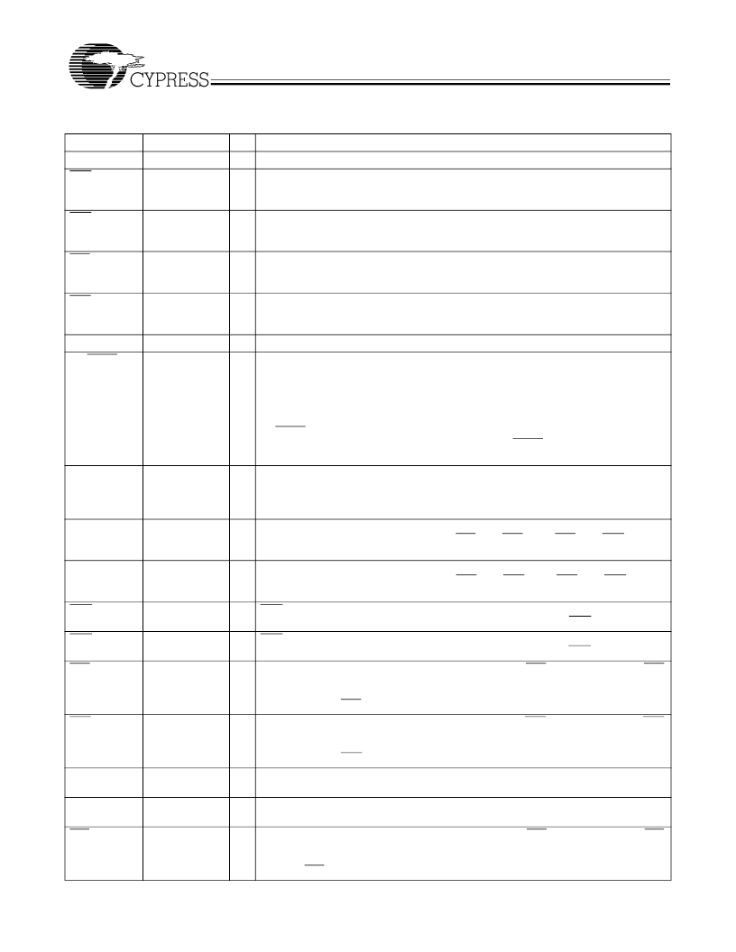
Pin Definitions
Signal Name
A
0
–
35
AEA
Description
Port A Data
Port A Almost
Empty Flag
I/O
I/O
O
Function
36-bit bidirectional data port for side A.
Programmable Almost Empty flag synchronized to CLKA. It is LOW when the number
of words in FIFO2 is less than or equal to the value in the Almost Empty A offset register,
X2.
Programmable Almost Empty flag synchronized to CLKB. It is LOW when the number
of words in FIFO1 is less than or equal to the value in the Almost Empty B offset register,
X1.
Programmable Almost Full flag synchronized to CLKA. It is LOW when the number of
empty locations in FIFO1 is less than or equal to the value in the Almost Full A offset
register, Y1.
Programmable Almost Full flag synchronized to CLKB. It is LOW when the number of
empty locations in FIFO2 is less than or equal to the value in the Almost Full B offset
register, Y2.
36-bit bidirectional data port for side B.
This is a dual-purpose pin. During Master Reset, a HIGH on BE will select Big Endian
operation. In this case, depending on the bus size, the most significant byte or word on
Port A is read from Port B first (A-to-B data flow) or written to Port B first (B-to-A data
flow). A LOW on BE will select Little Endian operation. In this case, the least significant
byte or word on Port A is read from Port B first (for A-to-B data flow) or written to Port
B first (B-to-A data flow). After Master Reset, this pin selects the timing mode. A HIGH
on FWFT selects CY Standard mode, a LOW selects First-Word Fall-Through mode.
Once the timing mode has been selected, the level on FWFT must be static throughout
device operation.
A HIGH on this pin enables either byte or word bus width on Port B, depending on the
state of SIZE. A LOW selects long-word operation. BM works with SIZE and BE to
select the bus size and endian arrangement for Port B. The level of BM must be static
throughout device operation.
CLKA is a continuous clock that synchronizes all data transfers through Port A and can
be asynchronous or coincident to CLKB. FFA/IRA, EFA/ORA, AFA, and AEA are all
synchronized to the LOW-to-HIGH transition of CLKA.
CLKB is a continuous clock that synchronizes all data transfers through Port B and can
be asynchronous or coincident to CLKA. FFB/IRB, EFB/ORB, AFB, and AEB are all
synchronized to the LOW-to-HIGH transition of CLKB.
CSA must be LOW to enable a LOW-to HIGH transition of CLKA to read or write on
Port A. The A
0
–
35
outputs are in the high-impedance state when CSA is HIGH.
CSB must be LOW to enable a LOW-to HIGH transition of CLKB to read or write on
Port B. The B
0
–
35
outputs are in the high-impedance state when CSB is HIGH.
This is a dual-function pin. In the CY Standard mode, the EFA function is selected. EFA
indicates whether or not the FIFO2 memory is empty. In the FWFT mode, the ORA
function is selected. ORA indicates the presence of valid data on A
0
–
35
outputs, avail-
able for reading. EFA/ORA is synchronized to the LOW-to-HIGH transition of CLKA.
This is a dual-function pin. In the CY Standard mode, the EFB function is selected. EFB
indicates whether or not the FIFO1 memory is empty. In the FWFT mode, the ORB
function is selected. ORB indicates the presence of valid data on B
0
–
35
outputs, avail-
able for reading. EFB/ORB is synchronized to the LOW-to-HIGH transition of CLKB.
ENA must be HIGH to enable a LOW-to-HIGH transition of CLKA to read or write data
on Port A.
ENB must be HIGH to enable a LOW-to-HIGH transition of CLKB to read or write data
on Port B.
This is a dual-function pin. In the CY Standard mode, the FFA function is selected. FFA
indicates whether or not the FIFO1 memory is full. In the FWFT mode, the IRA function
is selected. IRA indicates whether or not there is space available for writing to the FIFO1
memory. FFA/IRA is synchronized to the LOW-to-HIGH transition of CLKA.
AEB
Port B Almost
Empty Flag
O
AFA
Port A Almost
Full Flag
O
AFB
Port B Almost
Full Flag
O
B
0
–
35
BE/FWFT
Port B Data
Big Endian/
First-Word Fall-
Through Select
I/O
I
BM
Bus Match
Select (Port A)
I
CLKA
Port A Clock
I
CLKB
Port B Clock
I
CSA
Port A Chip
Select
Port B Chip
Select
Port A Empty/
Output Ready
Flag
I
CSB
I
EFA/ORA
O
EFB/ORB
Port B Empty/
Output Ready
Flag
O
ENA
Port A Enable
I
ENB
Port B Enable
I
FFA/IRA
Port A Full/Input
Ready Flag
O
相關(guān)PDF資料 |
PDF描述 |
|---|---|
| CY7C43664 | 4K x36 x2 Bidirectional Synchronous FIFO w/ Bus Matching(4K x36 x2 雙向同步先進(jìn)先出帶總線(xiàn)匹配) |
| CY7C43684 | 16K x36 x2 Bidirectional Synchronous FIFO w/ Bus Matching(16K x36 x2 雙向同步先進(jìn)先出帶總線(xiàn)匹配) |
| CY7C43636 | 512 x36/x18x2 Tri Bus FIFO(512 x36/x18x2 三路總線(xiàn) 先進(jìn)先出) |
| CY7C43626 | 256 x36/x18x2 Tri Bus FIFO(256 x36/x18x2 三路總線(xiàn)先進(jìn)先出) |
| CY7C43646 | 1K x36/x18x2 Tri Bus FIFO(1K x36/x18x2 三路總線(xiàn) 先進(jìn)先出) |
相關(guān)代理商/技術(shù)參數(shù) |
參數(shù)描述 |
|---|---|
| CY7C43644AV-10AC | 制造商:Cypress Semiconductor 功能描述:FIFO Mem Sync Dual Depth/Width Bi-Dir 1K x 36 x 2 128-Pin TQFP |
| CY7C43663-15AC | 制造商:Rochester Electronics LLC 功能描述:- Bulk |
| CY7C43664-7AC | 制造商:Rochester Electronics LLC 功能描述:- Bulk |
| CY7C43682-15AC | 制造商:Rochester Electronics LLC 功能描述:- Bulk |
| CY7C43683-10AI | 制造商:Rochester Electronics LLC 功能描述:- Bulk |
發(fā)布緊急采購(gòu),3分鐘左右您將得到回復(fù)。