- 您現(xiàn)在的位置:買賣IC網(wǎng) > PDF目錄369673 > CSP1027 CSP1027 Voice Band Codec for Cellular Handset and Modem Applications PDF資料下載
參數(shù)資料
| 型號: | CSP1027 |
| 元件分類: | Codec |
| 英文描述: | CSP1027 Voice Band Codec for Cellular Handset and Modem Applications |
| 中文描述: | CSP1027語音頻帶編解碼器的蜂窩手機(jī)和調(diào)制解調(diào)器應(yīng)用 |
| 文件頁數(shù): | 43/64頁 |
| 文件大?。?/td> | 937K |
| 代理商: | CSP1027 |
第1頁第2頁第3頁第4頁第5頁第6頁第7頁第8頁第9頁第10頁第11頁第12頁第13頁第14頁第15頁第16頁第17頁第18頁第19頁第20頁第21頁第22頁第23頁第24頁第25頁第26頁第27頁第28頁第29頁第30頁第31頁第32頁第33頁第34頁第35頁第36頁第37頁第38頁第39頁第40頁第41頁第42頁當(dāng)前第43頁第44頁第45頁第46頁第47頁第48頁第49頁第50頁第51頁第52頁第53頁第54頁第55頁第56頁第57頁第58頁第59頁第60頁第61頁第62頁第63頁第64頁

Lucent Technologies Inc.
Data Sheet
December 1999
CSP1027 Voice Band Codec for
Cellular Handset and Modem Applications
43
7 Application Information
(continued)
7.4.5 Frequency Accuracy Considerations
For most applications, clock frequency errors in the hundreds of parts per million (ppm) can be tolerated with no
adverse effect. However, for applications where precise frequency tolerance on the order 100 ppm is required, care
must be taken in the choice of external components (crystal and capacitors) as well as in the layout of the printed-
circuit board. Several factors determine the frequency accuracy of a crystal-based oscillator circuit. Some of these
factors are determined by the properties of the crystal itself. Generally, a low-cost, standard crystal will not be suffi-
cient for a high-accuracy application, and a custom crystal must be specified. Most crystal manufacturers provide
extensive information concerning the accuracy of their crystals, and an applications engineer from the crystal ven-
dor should be consulted prior to specifying a crystal for a given application.
In addition to absolute, temperature, and aging tolerances of a crystal, the operating frequency of a crystal is also
determined by the total load capacitance seen by the crystal. When ordering a crystal from a vendor, it is neces-
sary to specify a load capacitance at which the operating frequency of the crystal will be measured. Variations in
this load capacitance due to temperature and manufacturing variations will cause variations in the operating fre-
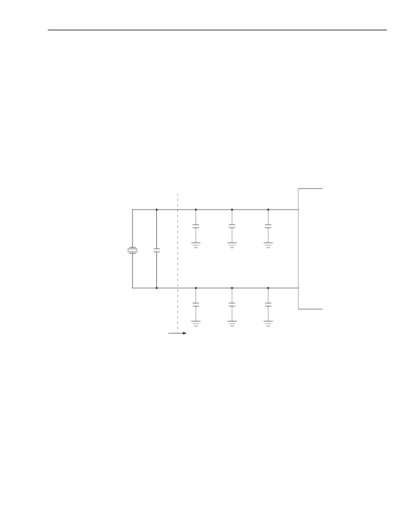
quency of the oscillator. Figure 36 illustrates some of the sources of this variation.
Notes:
C
EXT
=
External load capacitor (one each required for XLO and XHI).
C
D
=
Parasitic capacitance of the CSP1027 itself.
C
B
=
Parasitic capacitance of the printed-wiring board.
C
0
=
Parasitic capacitance of crystal (not part of C
L
, but still a source of frequency variation).
Figure 36. Components of Load Capacitance for Crystal Oscillator
The load capacitance, C
L
, must be specified to the crystal vendor. The crystal manufacturer will cut the crystal so
that the frequency of oscillation will be correct when the crystal sees this load capacitance. Note that C
L
refers to a
capacitance seen across the crystal leads, meaning that for the circuit shown in Figure 36, C
L
is the series combi-
nation of the two external capacitors (C
EXT
/2) plus the equivalent board and device strays (C
B
/2 + C
D
/2). For exam-
ple, if 10 pF external capacitors were used and parasitic capacitance is neglected, then the crystal should be
specified for a load capacitance of 5 pF. If the load capacitance deviates from this value due to the tolerance on the
external capacitors or the presence of strays, then the frequency will also deviate.
XLO
XHI
XTAL
C
D
C
B
C
EXT
C
D
C
B
C
EXT
C
L
C
O
5-7615 (F)
相關(guān)PDF資料 |
PDF描述 |
|---|---|
| CT1469-2 | CT1469-2 MIL-STD-1397 Type E 10MHz Transceiver |
| CT1496-2 | CT1496-2 MIL-STD-1397 Type E 10MHz Low Level Serial Manchester 32 Bit Encoder |
| CT1508-2 | CT1508-2 MIL-STD-1397 Type E 10MHz Serial Manchester 4-Bit SIS / SOS Decoder |
| CT1611 | DMA Controller with Buffer Memory,MIL-STD-1750A Compatible |
| CT1611-FP | DMA Controller with Buffer Memory,MIL-STD-1750A Compatible |
相關(guān)代理商/技術(shù)參數(shù) |
參數(shù)描述 |
|---|---|
| CSP1027J | 制造商:未知廠家 制造商全稱:未知廠家 功能描述:Linear CODEC |
| CSP1027-J11-DB | 制造商:Alcatel-Lucent 功能描述: |
| CSP1027S | 制造商:未知廠家 制造商全稱:未知廠家 功能描述:Linear CODEC |
| CSP1027-S11-DB | 制造商:Rochester Electronics LLC 功能描述:- Bulk |
| CSP1034AH | 制造商:未知廠家 制造商全稱:未知廠家 功能描述:Telecommunication IC |
發(fā)布緊急采購,3分鐘左右您將得到回復(fù)。